Fuel cell system

a fuel cell and system technology, applied in the field of fuel cell systems, can solve the problems of unnecessary supply of regulators, and achieve the effects of preventing damage to the fuel cell caused by pressure, and reducing the pressure on the fuel cell

Active Publication Date: 2009-06-18
HONDA MOTOR CO LTD
View PDF13 Cites 30 Cited by
  • Summary
  • Abstract
  • Description
  • Claims
  • Application Information

AI Technical Summary

Benefits of technology

[0021]In a conventional fuel cell vehicle, an anode gas supply channel is provided with a shutoff valve requiring to be shut whenever the vehicle stops, in order to prevent damage in the fuel cell caused by the pressure of the anode gas.
[0022]However, according to the present invention, the gas shutoff means shuts the space between the needle and the nozzle when the fuel cell vehicle stops and then the pressure of the third gas is less than the predetermined value. Thus, the pressure at the downstream side of the ejector decreases, and then the pressure in the fuel cell decreases. Therefore, damage in the fuel cell can be prevented automatically, so that the shutoff valve can be removed.
[0023]According to the present invention, pressure fluctuation is propagated to the second and the third fluid chambers through the diaphragms formed at both sides of the first fluid chamber when the pressure of the first gas fluctuates. Thus, the pressure fluctuation affects the second gas introduced into the second fluid chamber and the third gas introduced into the third fluid chamber, but the directions in which the needle and the nozzle move relatively are opposite, whereby the effect of this pressure fluctuation on the second and the third gases is offset. Thus, the force to move the nozzle and the needle relatively depends on only the differential pressure between the second fluid chamber and the third fluid chamber. Therefore, the constant flow of gas to be delivered from the ejector can be maintained.

Problems solved by technology

In the result, it is unnecessary to provide with a regulator controlling the pressure of the first gas introduced into the first fluid chamber.

Method used


Image

  • Fuel cell system
  • Fuel cell system
  • Fuel cell system

Examples


Embodiment Construction

[0029]Hereinafter, embodiments of the present invention are described with reference to the drawings.

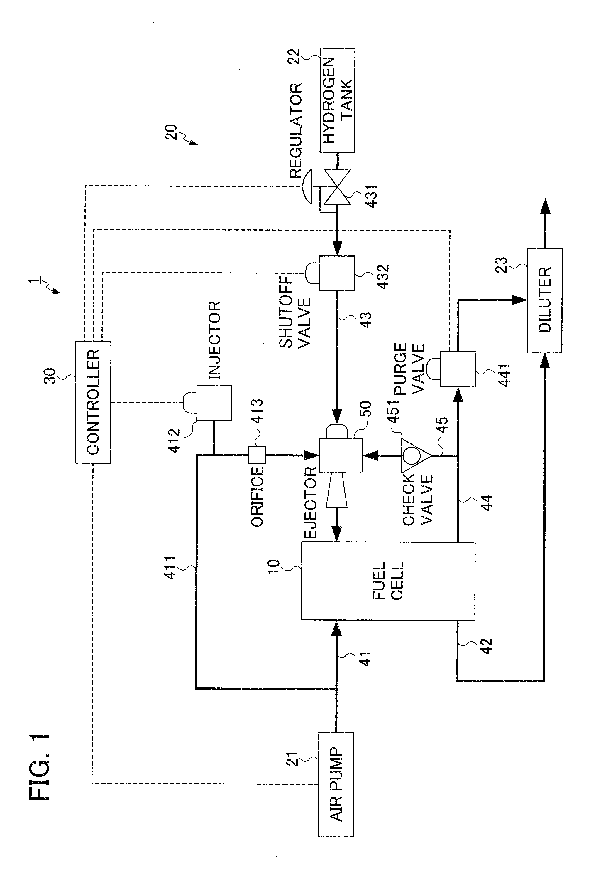
[0030]FIG. 1 is a block diagram illustrating a fuel cell system 1 employing an ejector according to one embodiment of the present invention.

[0031]The fuel cell system 1 is mounted to a vehicle and provided with a fuel cell 10 producing power by reacting reactive gas, a supply device 20 supplying hydrogen gas and air to the fuel cell 10, and a controller 30 controlling the fuel cell 10 and the supply device 20.

[0032]Such the fuel cell 10 generates electric power by electrochemical reaction caused by supplying hydrogen gas as anode gas to the anode (positive) electrode side and oxygenated air as cathode gas to a cathode (negative) electrode side.

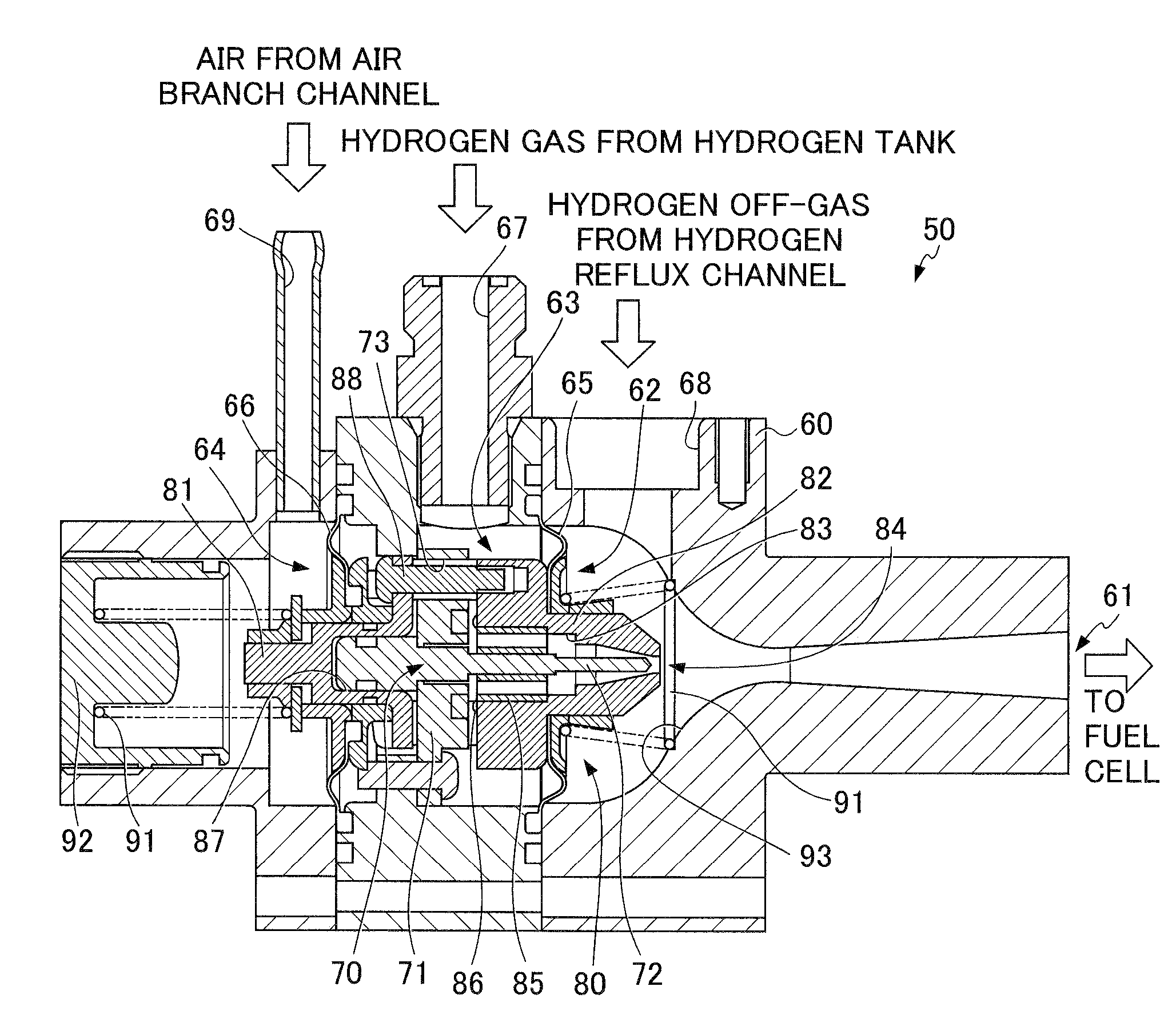
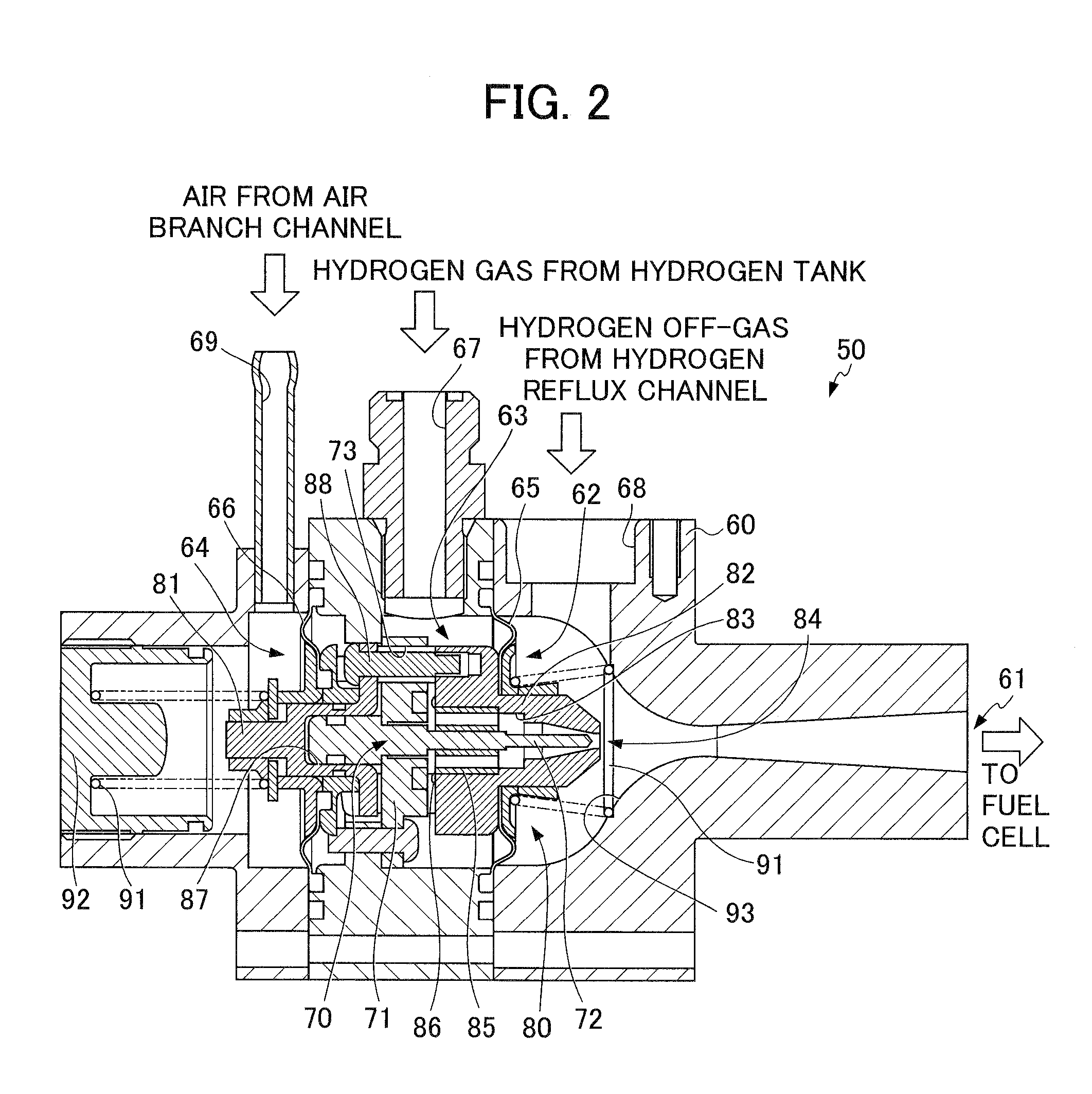
[0033]The supply device 20 is configured to include an air pump 21 supplying air to the cathode electrode side of the fuel cell 10, a hydrogen tank 22 as the hydrogen gas supply source and an ejector 50 that supply hydrogen gas to the anode ele...


PUM

PropertyMeasurementUnit
pressureaaaaaaaaaa
areasaaaaaaaaaa
electric poweraaaaaaaaaa

Abstract

An ejector is provided with a first fluid chamber into which hydrogen gas is introduced; a rod-shaped needle; a nozzle exhausting hydrogen gas introduced into the first fluid chamber from an exhaust port; a second fluid chamber into which hydrogen off-gas is introduced; a diffuser provided at the exhaust port of the nozzle; and a third fluid chamber into which air is introduced. The first fluid chamber is provided between the second fluid chamber and the third fluid chamber. The first diaphragm 65 separates the first fluid chamber and the second fluid chamber and the second diaphragm separates the first chamber and the third fluid chamber. Then, the needle and the nozzle moves to approach each other by the pressure of air introduced into the third fluid chamber and isolate each other by the pressure of hydrogen off-gas introduced into the second fluid chamber.

Description

[0001]This application is based on and claims the benefit of priority from Japanese Patent Application No. 2007-320911, filed on 12 Dec. 2007, the content of which is incorporated herein by reference.BACKGROUND OF THE INVENTION[0002]1. Field of the Invention[0003]The present invention relates to a fuel cell system. In particular, it relates to a fuel cell system mounted to an automobile.[0004]2. Related Art[0005]In recent years, a fuel cell system gains a spotlight as a new power source of an automotive vehicle. For example, a fuel cell system is provided with a fuel cell producing electric power from chemical reaction of reactive gas, a reactive gas supply device supplying reactive gas to the fuel cell through a reactive gas channel, and a control device controlling this reactive gas supply device.[0006]For example, the fuel cell consists of a plurality, e.g., tens or hundreds, of stacked cells. Each of the cells is configured so that a pair of separators sandwiching a membrane ele...

Claims


Application Information

Patent Timeline
Patent Type & Authority Applications(United States)
IPC IPC(8): F04F5/14H01M8/04F04F5/46F04F5/48
CPCF04F5/461F04F5/54Y02E60/50H01M2008/1095H01M8/04097H01M8/04104
Inventor FUKUMA, KAZUNORI
Owner HONDA MOTOR CO LTD
Why Eureka
Try Eureka