

Transmitter and communication apparatus
- Summary
- Abstract
- Description
- Claims
- Application Information
AI Technical Summary
Benefits of technology
Problems solved by technology
Method used
Image

Examples
first embodiment
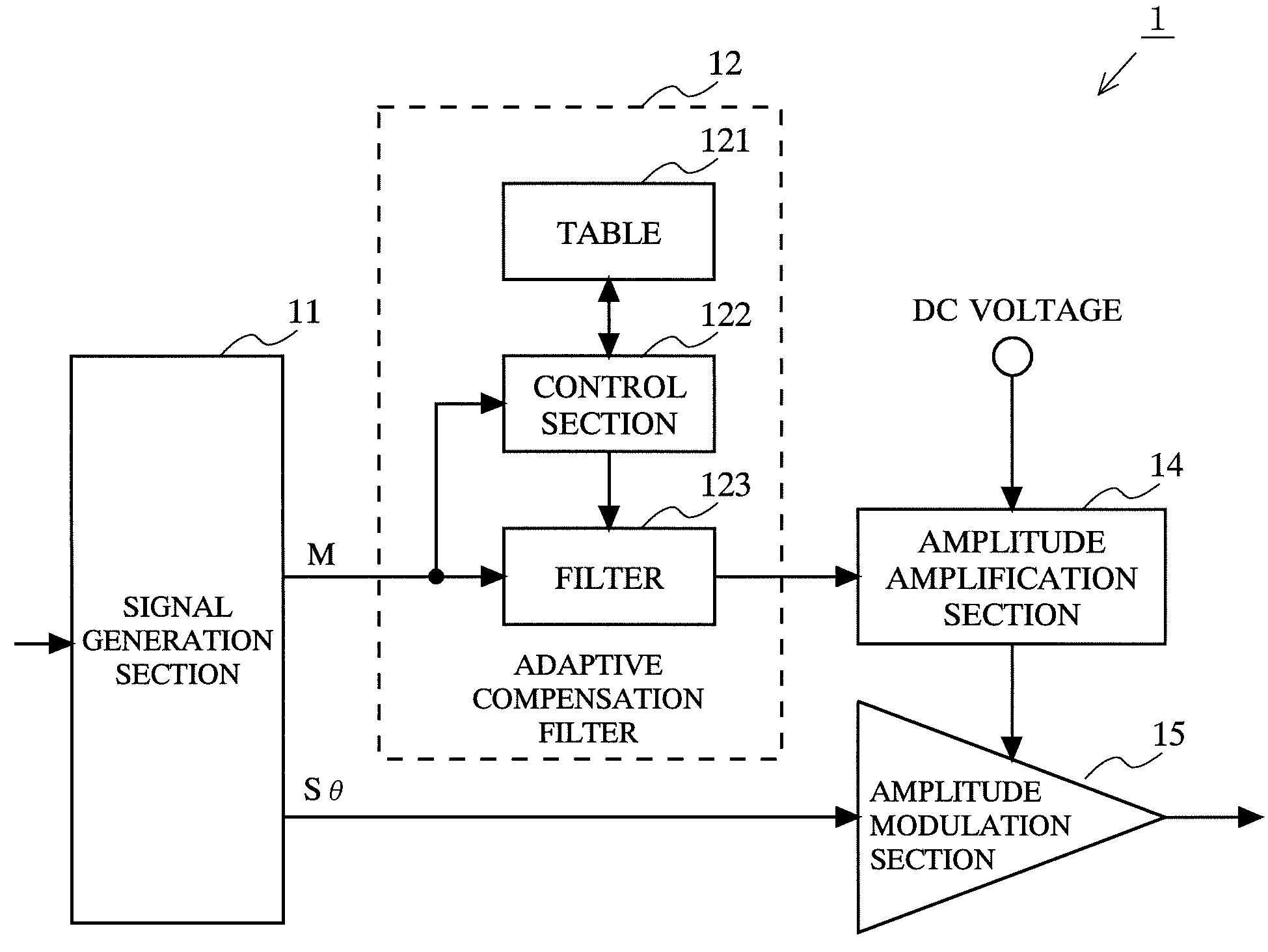
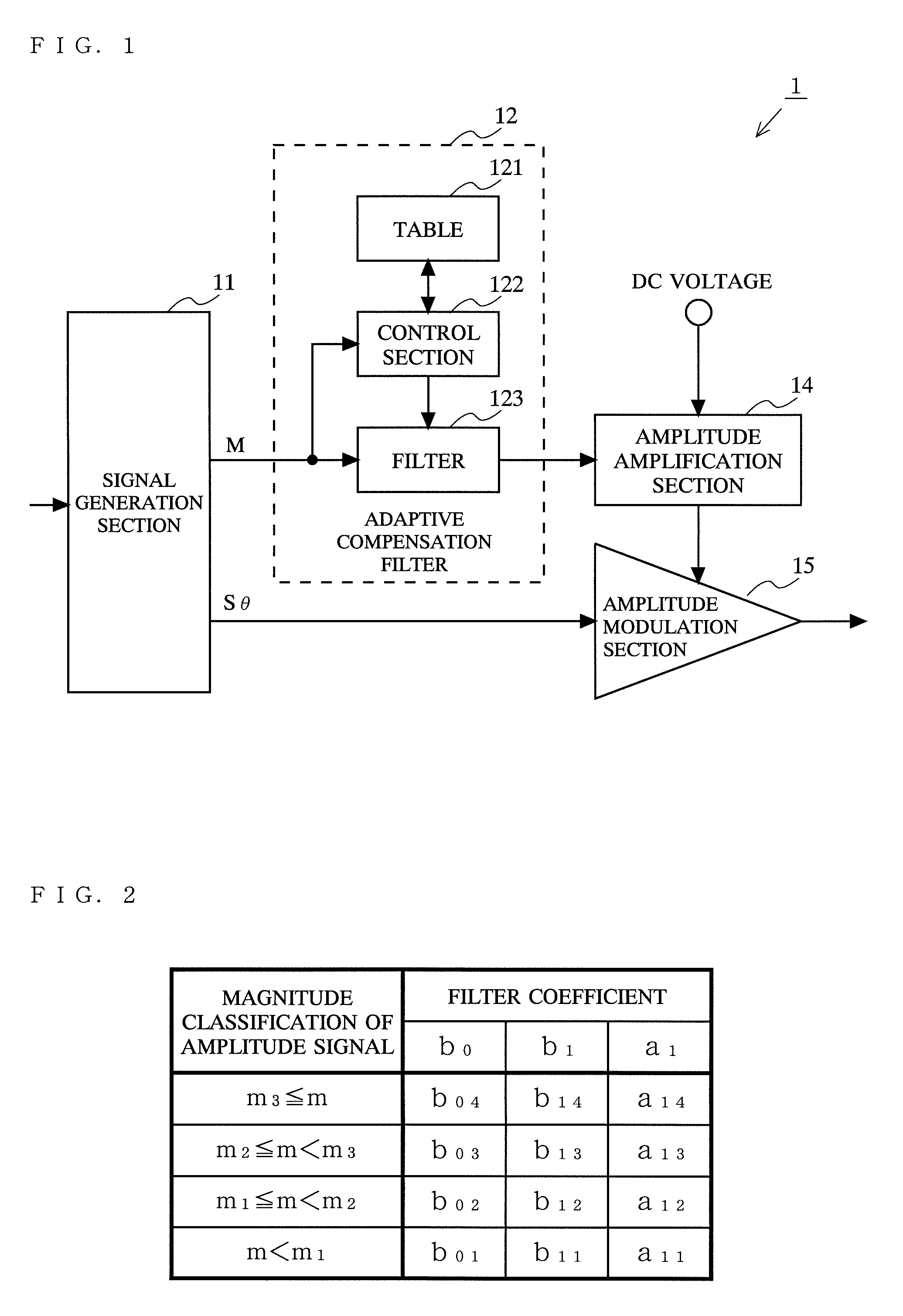
[0051]FIG. 1 is a diagram showing the structure of a transmitter 1 according to a first embodiment of the present invention. Referring to FIG. 1, the transmitter 1 includes a signal generation section 11, an adaptive compensation filter 12, an amplitude amplification section 14, and an amplitude modulation section 15. The adaptive compensation filter 12 includes a table 121, a control section 122, and a filter 123.
[0052]The signal generation section 11 outputs an amplitude signal M and an angle-modulated signal Sθ based on an amplitude component and a phase component that are obtained by performing signal processing on input data. The amplitude signal M is subjected to waveform shaping corresponding to the magnitude of the amplitude signal M in the adaptive compensation filter 12 and then is inputted to the amplitude amplification section 14. The amplitude amplification section 14 outputs a signal controlled by the inputted amplitude signal. Typically, the amplitude amplification se...
second embodiment
[0073]FIG. 10 is a diagram showing the structure of a transmitter 2 according to a second embodiment of the present invention. Referring to FIG. 10, the transmitter 2 includes a signal generation section 21, a multiplication section 23, an adaptive compensation filter 12, an amplitude amplification section 14, and an amplitude modulation section 15. The adaptive compensation filter 12 includes a table 121, a control section 122, and a filter 123.
[0074]The transmitter 2 according to the second embodiment is different from the transmitter 1 according to the first embodiment in that the transmitter 2 has the signal generation section 21 and the multiplication section 23. These different components of the transmitter 2 will be described below, while the same components as those of the transmitter 1 will be denoted by the same numerals and will not be described.
[0075]The signal generation section 21 outputs power information P set based on a baseband, as well as outputting an amplitude s...
third embodiment
[0077]FIG. 11 is a diagram showing the structure of a transmitter 3 according to a third embodiment of the present invention. Referring to FIG. 11, the transmitter 3 includes a signal generation section 21, an adaptive compensation filter 32, a multiplication section 33, an amplitude amplification section 14, and an amplitude modulation section 15. The adaptive compensation filter 32 includes a table 321, a control section 322, and a filter 323.
[0078]The transmitter 3 according to the third embodiment is different from the transmitter 2 according to the second embodiment in that the transmitter 3 has the adaptive compensation filter 32 and the multiplication section 33. These different components of the transmitter 3 will be described below, while the same components as those of the transmitters 1 and 2 will be denoted by the same numerals and will not be described.
[0079]In the table 321, the filter coefficients used by the filter 323 are each stored in accordance with the power inf...
PUM
 Abstract
Description
Claims
Application Information