
Method, apparatus, and computer program product for signaling allocation of neighbor cells

Active Publication Date: 2009-06-18
NOKIA TECHNOLOGLES OY
View PDF11 Cites 92 Cited by
  • Summary
  • Abstract
  • Description
  • Claims
  • Application Information

AI Technical Summary

Benefits of technology

[0018]According to recent developments in this field, time division multiplexing (TDM) of Multimedia Broadcast Multimedia Services (MBMS) and unicasting of data channel (Physical Downlink Shared Channel PDSCH) are done on a sub-frame basis. The unicast control channel (Physical Downlink Control Channel or PDCCH) together with downlink unicast pilot (cell specific RS) can be TDM multiplexed with MBSFN in the same sub-frame (so-called MBSFN sub-frame) in case of a mixed MBSFN or unicast carrier. In such MBSFN sub-frames, the PDCCH (with cell-specific pilot) is transmitted in the first, or in the first two, OFDM symbols and MBSFN (multi-cell traffic and pilot) is transmitted in the rest of the sub-frame's OFDM symbols. Furthermore, according to recent developments, MBSFN should not be transmitted in sub-frame #0 and #5 (i.e. Synchronization Channel or SCH sub-frames), so that UE can confidently use cell-specific RS at least in these sub-frames for measurements.
[0020]Providing full information regarding MBSFN or unicast sub-frame allocation in neighbor cells via own cell would be costly from the overhead or signaling point of view. The present invention therefore includes an efficient method to provide information about MBSFN or unicast allocation in neighbor cells, and to maximize the accuracy of mobility-related neighbor cell measurements by maximizing the number of RS resource elements eligible for UE mobility measurements of neighbor cells.

Problems solved by technology

Many features of the third generation (3G) mobile telecommunications system have already been established, but many other features have yet to be perfected.
However, that technique is very costly from the overhead point of view, because the P-BCH is a very robust channel and each P-BCH bit consumes a non-negligible part of a cell's capacity.
Furthermore, for measuring RS from neighbor cells, this requires that the P-BCH from neighbor cells be received before and during measurements which might be unreliable and adds extra complexity.
However, according to that technique, the number of RS elements eligible for measurements is always reduced by a factor of 4, which will incur measurement inaccuracy.

Method used


Image

  • Method, apparatus, and computer program product for signaling allocation of neighbor cells
  • Method, apparatus, and computer program product for signaling allocation of neighbor cells
  • Method, apparatus, and computer program product for signaling allocation of neighbor cells

Examples


Embodiment Construction

[0030]A preferred embodiment of the present invention will now be described. This is merely to illustrate one way of implementing the invention, without limiting the scope or coverage of what is described elsewhere in this application.

[0031]As mentioned, each cell transmits an indicator (preferably only one bit) of the difference in unicast or MBSFN sub-frame allocation between the own cell and neighbor cells. The indicator is broadcast on a common channel, preferably a dynamic broadcast channel. The indicator is set and signals whether unicast or MBSFN allocation in neighbor cells is the same or not compared to the own cell

[0032]An example of the present invention is shown in FIG. 3, where the indicator would be the same for all cells of a Node B: neighbor cells of Node B 1 have different unicast or MBSFN allocations. In consequence, the indicator broadcasted in the cells of Node B 1 is on. Node B 1 is aware of MBSFN or unicast allocation in cells of the group of (6) surrounding No...


PUM


Abstract

A method, user equipment, network device, and software product employ indicators from a plurality of respective cells to indicate a difference, if any, regarding allocation in the respective cell as compared to neighbor cells. Mobility measurements are then performed according to the indicators, and also on the basis of configuration of a cell where the measurements are performed.

Description

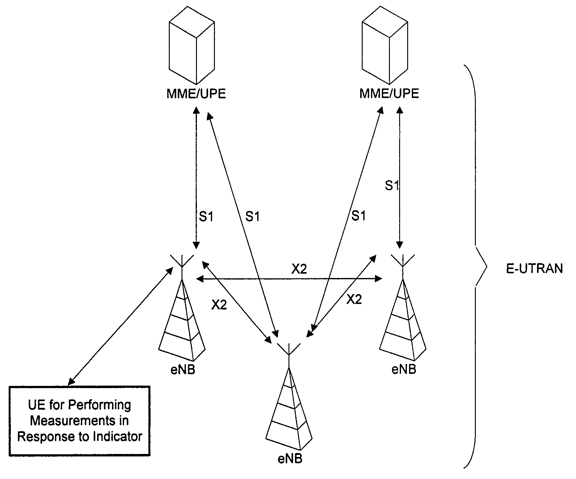
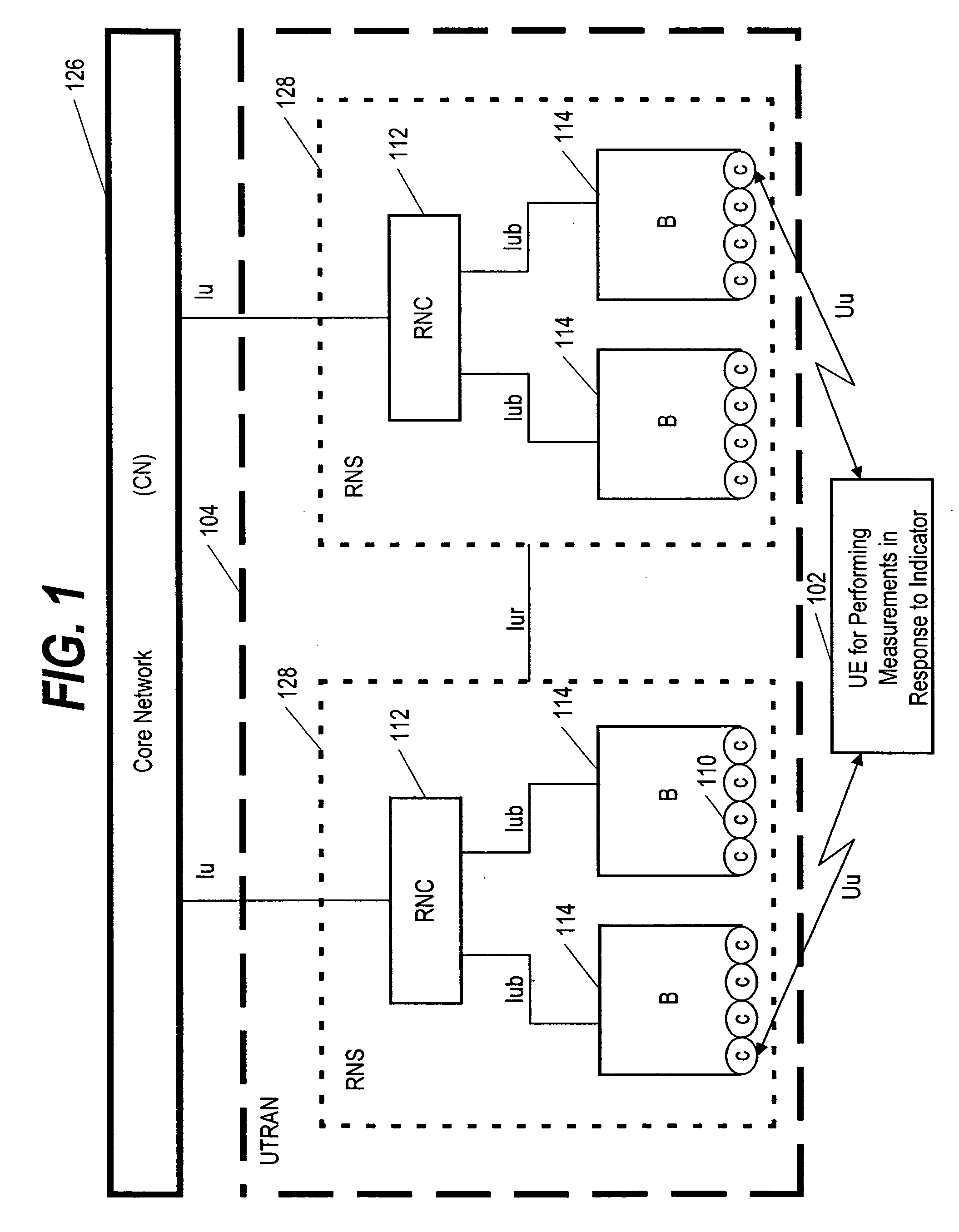
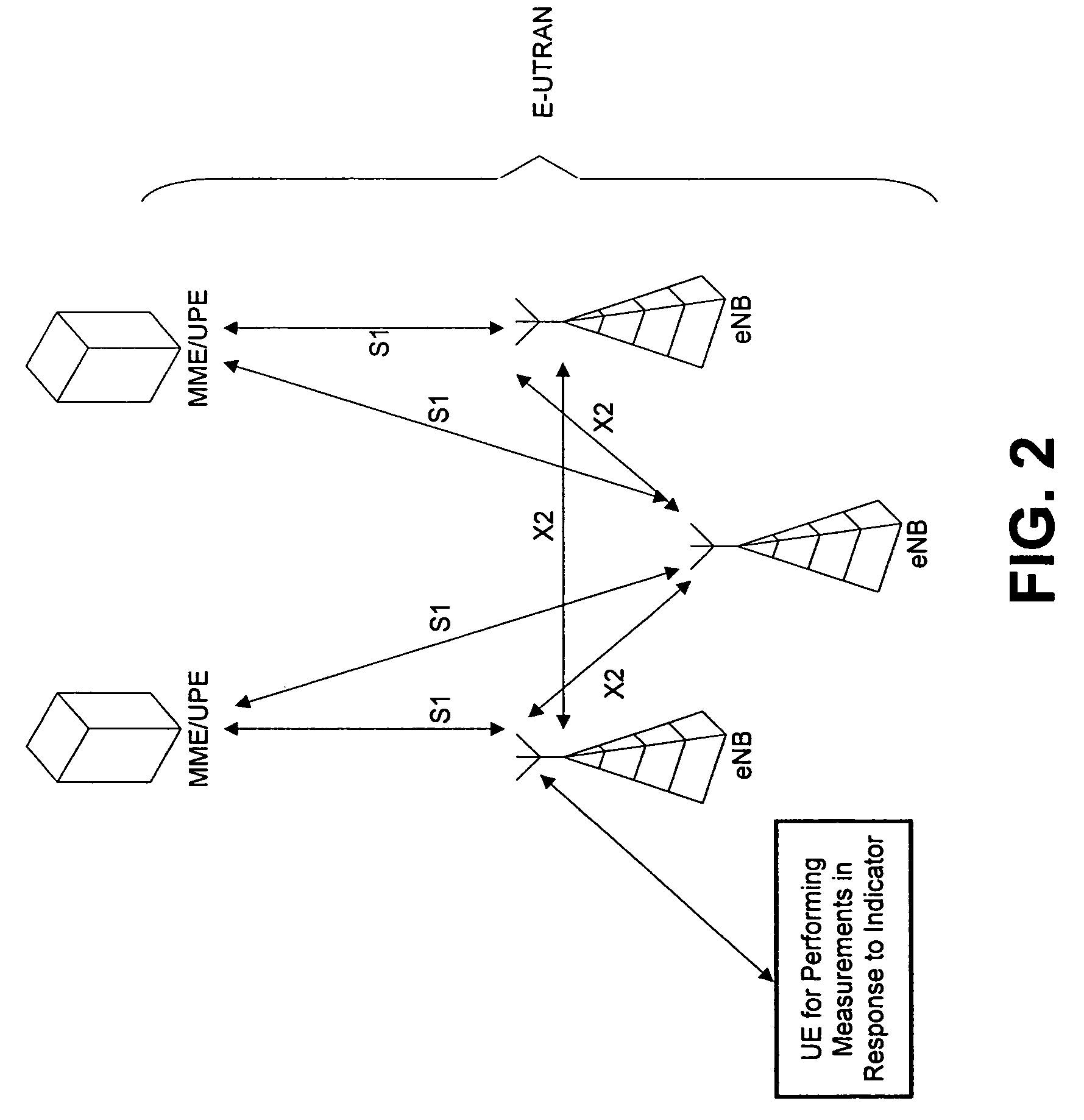
CROSS REFERENCE TO RELATED APPLICATION[0001]This application claims priority to U.S. Provisional Application 60 / 927,362 filed 2 May 2007.FIELD OF THE INVENTION[0002]The invention relates to the field of wireless telecommunications. More particularly, the present invention pertains to cell allocation.BACKGROUND OF THE INVENTION[0003]The telecommunications industry is in the process of developing a new generation of flexible and affordable communications that includes high-speed access while also supporting broadband services. Many features of the third generation (3G) mobile telecommunications system have already been established, but many other features have yet to be perfected.[0004]One of the systems within the third generation of mobile communications is the Universal Mobile Telecommunications System (UMTS) which delivers voice, data, multimedia, and wideband information to stationary as well as mobile customers. As can be seen in FIG. 1, the UMTS architecture consists of user eq...

Claims


Application Information

Patent Timeline
IPC IPC(8): H04W72/00H04B7/00H04W4/06H04W48/16
CPCH04J11/0093H04L5/0058H04W48/16H04W4/06H04W36/302H04W16/02H04W16/24H04W72/0446H04W72/04H04W36/30H04W48/12H04W36/0061H04W24/10H04W72/23H04W72/541
Inventor ANGELOW, IWAJLOCHMIEL, MIESZKOKRAUSE, JORNVISURI, SAMULI
Owner NOKIA TECHNOLOGLES OY
Learn More