
Surgical Drill For Providing Holes At An Angle

Inactive Publication Date: 2009-06-18
KARL STORZ GMBH & CO KG
View PDF12 Cites 64 Cited by
  • Summary
  • Abstract
  • Description
  • Claims
  • Application Information

AI Technical Summary

Benefits of technology

[0010]It is a further object of the present invention to provide a surgical drill which allows a user to drill a tunnel in a femur at an angle to a tunnel in the tibia.
[0011]It is yet a further object of the present invention to provide a drill guide having a head that is angularly adjustable relative to the body, thus allowing a user to drill a tunnel in a femur at an angle to a tunnel in the tibia.
[0013]In addition, the drill guide may also comprise an actuator, comprising a rod, a screw having external threads, and a knob threadably connected to the screw, for adjusting the angular orientation of the head with respect to the body. At a distal end, the rod may be connected to the head of the drill guide and may be connected at a proximal end to the screw. The rod may pass through the body of the drill guide. Rotation of the knob may cause the screw and the rod to advance in a distal direction or retract in a proximal direction, further causing the head to rotate about a pivot point. To allow for rotation of the head, the rod may be connected to the head at a point radially spaced from the pivot point. In one embodiment, clockwise rotation of said knob causes the screw and the rod to advance in a distal direction, further causing the head to rotate clockwise about a pivot point. In another embodiment, counter-clockwise rotation of the knob causes the screw and the rod to retract in a proximal direction, further causing the head to rotate counter-clockwise about a pivot point.

Problems solved by technology

Damage to ligaments, such as anterior cruciate ligaments (ACL) and the posterior cruciate ligaments (PCL), cartilage, and tendons has become a relatively common occurrence and often requires surgical repair.
One problem associated with this technique is locating the proper position and angle for drilling the tunnel in the femur (femoral tunnel).
It is undesirable to ream through the back wall and in many cases the chosen fixation method will not work if this occurs.
Yet, this angle is difficult to reach when using a traditional over the top guide in the tibial tunnel, so some surgeons are recommending using a second low medial portal to place the over the top guide.
This allows for more lateral positioning in the AP plane, but, consequently, starting more superior decreases the angle of pin placement in the lateral plane, increasing the chance of reaming through the back wall of the femur.
While the medial portal can be used, and has the advantage of allowing for a more lateral femoral tunnel, it has several disadvantages that make it undesirable.
Notably, using the medial portal involves making a second incision in the tissue, which results in unnecessary fluid loss and an additional scar.
Furthermore, in order to use the medial portal, hyperflexion of the knee must be performed which is sometimes difficult to do.
Last, as stated above, using the medial portal increases the chance of reaming through the back wall of the femur which can make it difficult or impossible to properly secure the graft ligament.

Method used


Image

  • Surgical Drill For Providing Holes At An Angle
  • Surgical Drill For Providing Holes At An Angle
  • Surgical Drill For Providing Holes At An Angle

Examples


Embodiment Construction

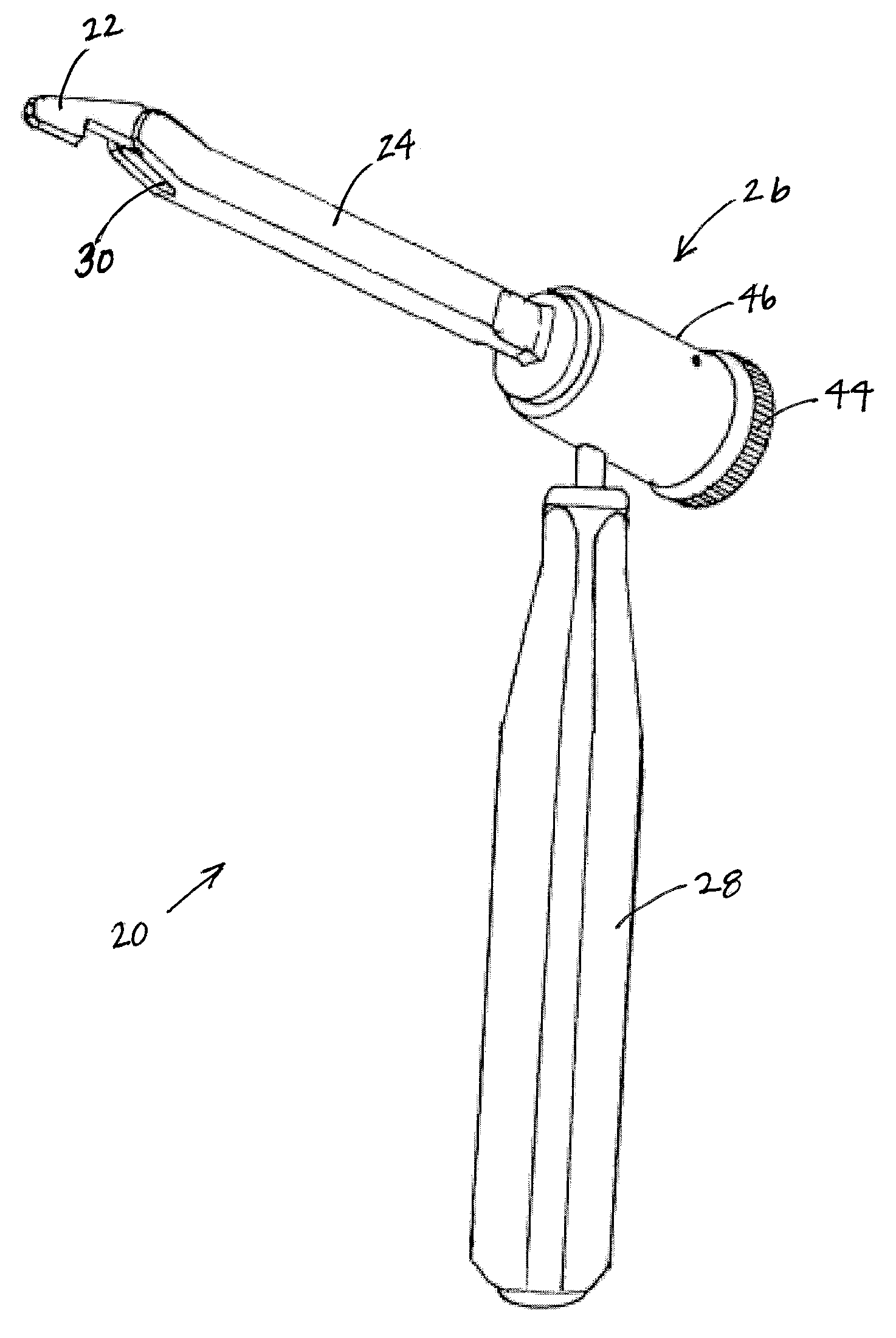
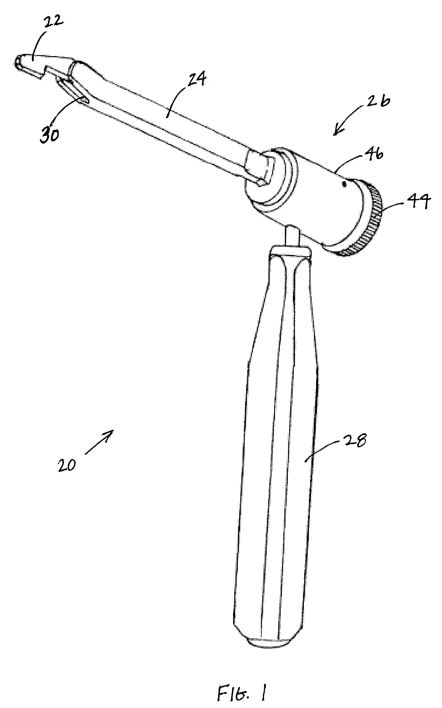
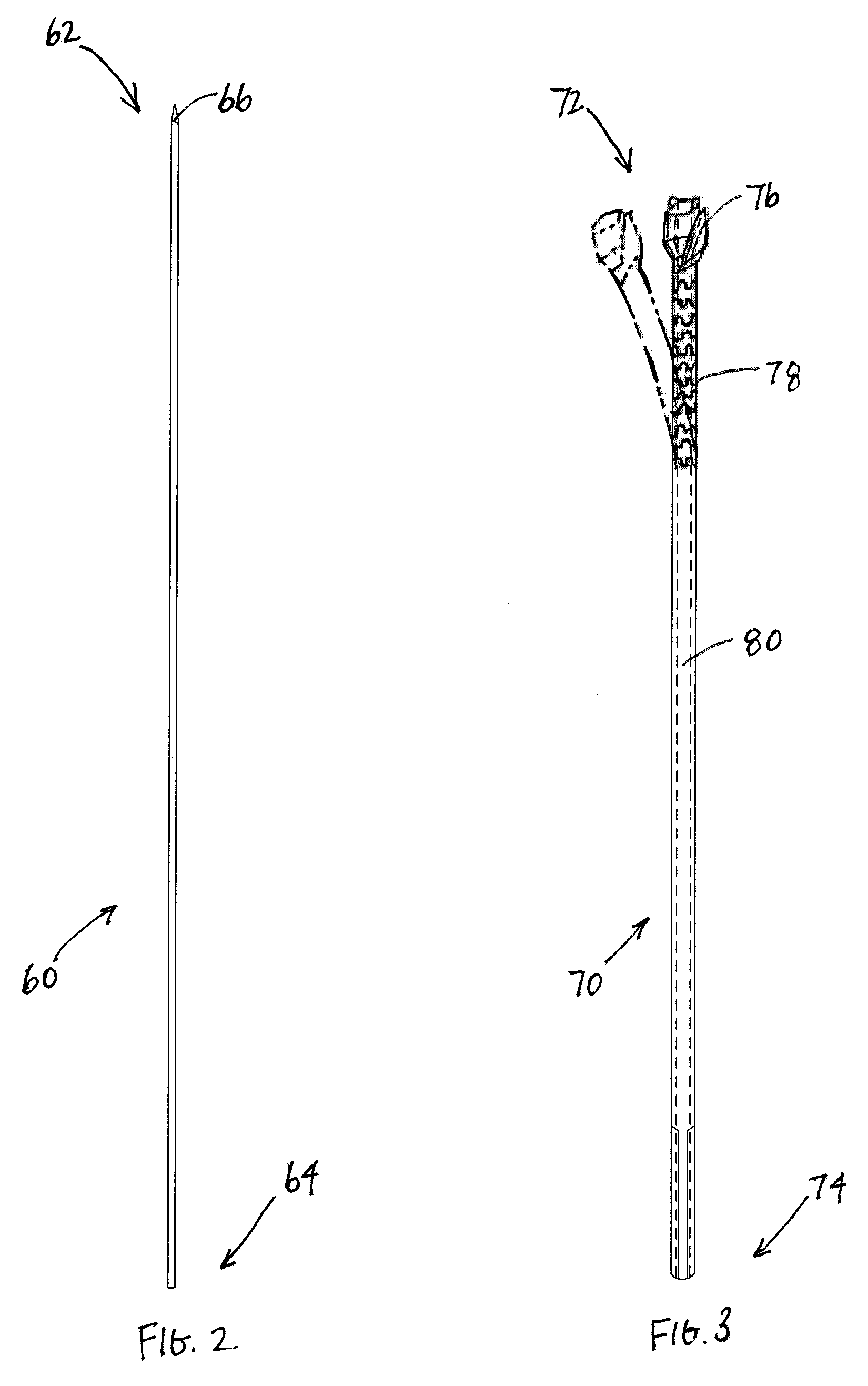
[0029]FIGS. 1-3 depict the surgical drill in accordance with the present invention, which comprises drill guide 20, pin 60, and flexible drill 70. The surgical drill of the present invention provides a second hole along an axis y that may be at an angle relative to a first hole along an axis x. More specifically, particularly in view of the problems associated with the prior art described herein, the surgeon can drill a tunnel in the femur at an angle relative to a tunnel in the tibia. Because the surgeon can access the femur via the tunnel in the tibia, the surgical drill of the present invention obviates the need for a second hole in the tissue and also makes placement of femoral tunnel 90 more precise for securement of the ligament or tendon graft within the tunnel. As discussed in the prior art, placement of the femoral tunnel was problematic and poor placement may lead to improperly secured ligaments or tendons.

[0030]Referencing FIG. 1, drill guide 20 of the surgical drill comp...


PUM


Abstract

A surgical drill for providing holes at an angle for use in repair and replacement of the ACL is disclosed, generally comprising a drill guide having a head that is angularly adjustable with respect to a body, a flexible guide pin and a flexible drill. The adjustable head of the drill guide allows a surgeon to drill a hole in the femur at an angle to a tunnel provided in the tibia. Because the surgeon can access the femur via the hole in the tibia, the surgical drill of the present invention obviates the need for a second hole in the tissue and also makes placement of femur hole more precise for securement of the ligament or tendon graft within the hole.

Description

CROSS-REFERENCE TO RELATED APPLICATIONS[0001]The present application claims the benefit under 35 U.S.C. §119 (e) of the U.S. Provisional Patent Application Ser. No. 61 / 014,188 filed on Dec. 17, 2007.FIELD OF THE INVENTION[0002]The present invention relates to a surgical drill. More specifically, the invention relates to a surgical drill for providing a second hole in a bone at an angle relative to a first hole drilled in a bone.BACKGROUND OF THE INVENTION[0003]Damage to ligaments, such as anterior cruciate ligaments (ACL) and the posterior cruciate ligaments (PCL), cartilage, and tendons has become a relatively common occurrence and often requires surgical repair. Often, the ACL or the PCL is ruptured or torn as a result of physical activity and, consequently, various surgical procedures have been developed for replacing or reconstructing these ligaments.[0004]The knee joint is often repaired by substituting a harvested or synthetic replacement ligament for the damaged one. Commonly...

Claims


Application Information

Patent Timeline
IPC IPC(8): A61B17/00A61B17/58
CPCA61B17/1631A61B17/1764A61B17/1714A61B17/1675
Inventor HOMAN, BRADLEY MICHAELHART, RICKEY
Owner KARL STORZ GMBH & CO KG
Learn More