Quick repair method for continuous collapse of RC framework structure

A repair method and frame structure technology, applied in building maintenance, building structure, construction, etc., can solve problems such as economic loss, reconstruction cycle and long shutdown period, and achieve significant social benefits, short repair cycle, and improved economy Effect

Active Publication Date: 2016-05-11
HARBIN INST OF TECH
View PDF5 Cites 4 Cited by
  • Summary
  • Abstract
  • Description
  • Claims
  • Application Information

AI Technical Summary

Problems solved by technology

[0003] The purpose of the present invention is to solve the problems of economic loss caused by dismantling the entire structure, long reconstruction per...

Method used


Image

  • Quick repair method for continuous collapse of RC framework structure
  • Quick repair method for continuous collapse of RC framework structure
  • Quick repair method for continuous collapse of RC framework structure

Examples


specific Embodiment approach 1

[0027] Specific embodiment one: a kind of rapid repair method based on the continuous collapse of RC frame structure of this embodiment is specifically implemented according to the following steps:

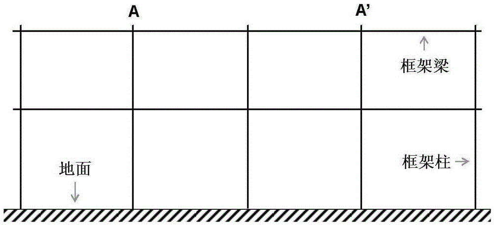
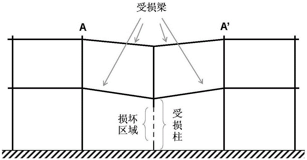
[0028] The continuous collapse of the RC frame structure refers to the downward deformation of the frame beam in the damaged column and the upper layer of the structure shown in Figure 1(a) after a certain column is damaged, as shown in Figure 1(b) ) shown in ; the damage location is the damaged column itself and the end area of ​​the beam in the AA' axis;

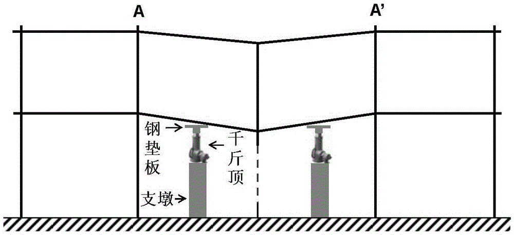
[0029] The equipment and materials required for the rapid repair method for the continuous collapse of the RC frame structure specifically include: buttresses, jacks, steel backing plates, steel bars, and grouting materials; wherein, the steel bars are used for longitudinal steel bars or for stirrups;

[0030] The steel backing plate is a square steel plate with the same size as the width of the damaged beam; the longitudinal ...

specific Embodiment approach 2

[0047] Embodiment 2: This embodiment differs from Embodiment 1 in that: the length of the steel pipe described in Step 1 is 4 cm. Other steps and parameters are the same as those in Embodiment 1.

specific Embodiment approach 3

[0048] Specific embodiment three: the difference between this embodiment and specific embodiment one or two is: in step 7, one end of the reinforcing bar of the planting bar is implanted into the minimum length l of the node at the beam-column fracture. min Press formula l min =max{0.3l s 10d100mm} calculation, where d is the nominal diameter of the implanted reinforcement (unit: mm), f y It is the design value of the tensile strength of the implanted steel bar (unit: N / mm 2 ), f bd is the design value of bond shear strength of planting glue (unit: N / mm 2 ); other steps and parameters are the same as those in Embodiment 1 or 2.


PUM

PropertyMeasurementUnit
Lengthaaaaaaaaaa
Lengthaaaaaaaaaa

Abstract

The invention discloses a quick repair method for continuous collapse of an RC framework structure. The invention relates to a repair method for the continuous collapse of the RC framework structure, and aims to solve the problems of large economic losses and long reconstruction cycle caused by the situation that when buildings are continuously collapsed, the whole structure needs to be dismantled. The method is realized through the following steps: I, building supporting systems each of which consists of a jack, a supporting pier and a steel base plate; II, supporting the bottoms of damaged columns and the bottoms of damaged beams with the built steel base plates; III, jacking up a collapsed structure to the elevation of a structure which is not collapsed; IV, supporting the bottom of each layer of the damaged beams above the damaged columns with the steel base plates; V, striking concrete at the region of the end part of a damaged beam till the concrete is crushed; VI, straightening a reinforcing bar which is not cracked in the damaged beam, and transecting a cracked reinforcing bar; VII, repairing the cracked reinforcing bar according to a tendon grafting method; VIII, bundling hoop tendons, supporting molds, casting grouting materials, and dismantling molds; IX, repairing the damaged columns; X, removing supporting piers, the jacks, the base plates, and the like under the damaged beams. The method disclosed by the invention is applied to the field of the continuous collapse of the RC framework structure.

Description

technical field [0001] The invention relates to a rapid repair method, in particular to a rapid repair device and method based on the continuous collapse of an RC frame structure. Background technique [0002] The collapse of buildings caused by accidental loads such as fire, vehicle impact, explosion, etc. is a continuous collapse, which is characterized in that the load directly causes damage to a certain component of the building, and then the building further undergoes a wider partial or overall collapse under the action of its own weight. For RC (Reinforced Concrete) frame structures, damage to columns will cause continuous collapse. For buildings designed in accordance with building design codes, in most cases, only the frame columns that are directly subjected to external loads will lose their function, and then large vertical deformations along the direction of the failed frame columns will occur, and beam ends will be damaged (concrete collapse , some steel bars ar...

Claims


Application Information

Patent Timeline
IPC IPC(8): E04G23/02
CPCE04G23/0218
Inventor 李爽单思镝翟长海刘坤谢礼立
Owner HARBIN INST OF TECH
Why Eureka
Try Eureka