Delivery system attachment

a delivery system and attachment technology, applied in the field of delivery systems, can solve the problems of long healing time of fractures and other orthopedic injuries, inability to support physiologic loading unaided, and significant stiffness of metals, so as to facilitate the transfer of substances and/or materials

Active Publication Date: 2009-06-18
WARSAW ORTHOPEDIC INC
View PDF110 Cites 473 Cited by
  • Summary
  • Abstract
  • Description
  • Claims
  • Application Information

AI Technical Summary

Benefits of technology

[0007]A delivery system for delivering a substance or material to a surgical site is provided. The delivery system comprises a covering and a substance to be retained within and delivered by the covering. Generally, the covering may be a single or multi-compartment structure capable of at least partially retaining a substance provided therein until the covering is placed at a surgical site. Upon placement, the covering facilitates transfer of the substance and / or materials surrounding the surgical site. The covering may participate in, control, or otherwise adjust, the release of the substance or penetration of the covering by surrounding materials, such as cells or tissues.

Problems solved by technology

While bone wounds can regenerate without the formation of scar tissue, fractures and other orthopedic injuries take a long time to heal, during which time the bone is unable to support physiologic loading unaided.
However, metal is significantly more stiff than bone.
Use of metal implants may result in decreased bone density around the implant site due to stress shielding.
Physiologic stresses and corrosion may cause metal implants to fracture.
Unlike bone, which can heal small damage cracks through remodeling to prevent more extensive damage and failure, damaged metal implants can only be replaced or removed.
Further, the implant is substantially complete at the time of implantation and thus provides little ability for customization, for example by the addition of autograft.
The use of bone grafts is generally limited by the available shape and size of grafts.
Traditional bone substitute materials and bone chips are more quickly remodeled but cannot immediately provide mechanical support.
In addition, while bone substitute materials and bone chips can be used to fill oddly shaped bone defects, such materials are not as well suited for wrapping or resurfacing bone.

Method used


Image

  • Delivery system attachment
  • Delivery system attachment
  • Delivery system attachment

Examples


embodiment 200

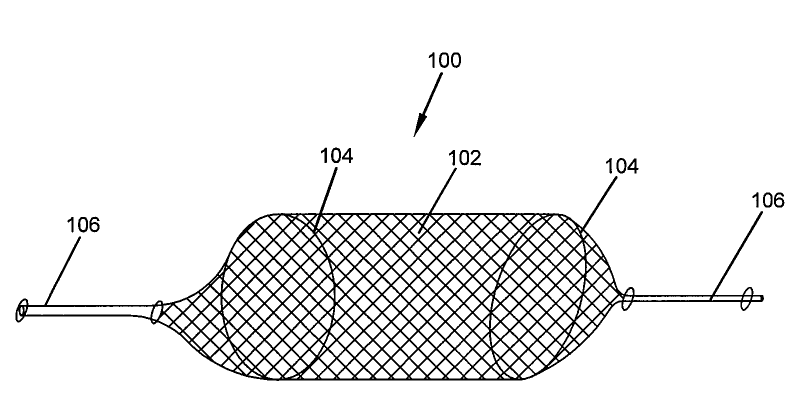
[0102]FIGS. 5a-5c illustrate a covering embodiment 200 having an elongated containment portion 202 for housing a substance for delivery, and having first and second ends 204, 206. One or both of the first and second ends 204, 206 may have an attachment mechanism 208. Any suitable attachment mechanism may be used. In the embodiment shown, each of the first and second ends 204, 206 comprises a tab attachment mechanism 208. One or both of the first and second ends 204, 206 further may be sealed. In the embodiment shown, the first end 204 is sealed. The seal 210 may comprise a portion of the tab 108, as shown, or may be separate from the tab 108. The seal 210 may have a width and a thickness suitable for maintaining a seal with the substance provided within the containment portion. For example, the seal 210 may have a length of approximately 0.6 cm, with the tab 208, including the seal 210, having a length of approximately 1.0 cm. Accordingly, the tab 108 is coextensive with the seal 21...

embodiment 60

[0115]FIG. 11 illustrates a nested dual-compartment embodiment 60. As shown, a second compartment 64 is provided within a first compartment 62. Selection of materials for provision in each of the first and second compartments may be based on release kinetics from the first compartment and from the second compartment (provided within the first compartment and thus also within the material provided in the first compartment). In one embodiment, smaller particles of a substance are provided within the first compartment and the first compartment accordingly comprises a tighter mesh while larger particles of a substance are provided within the second compartment and the second compartment comprises a looser mesh. Either or both of the first compartment 62 and the second compartment 64 may be preloaded. Alternatively, either or both of the first compartment 62 and the second compartment 64 may be left empty at manufacture for loading in the operating room or at the surgical site. In one em...

embodiment 80

[0137]FIG. 14a illustrates a tension band and covering embodiment 80 comprising a tension band or cable 82 and covering 84. As shown, the covering structure 84 is provided over the tension band or cable 82. The tension band 82 may comprise an osteogenic material, as described above, or may comprise other suitable material such as synthetic polymer, titanium, stainless steel, or other. The covering structure 84 may be filled with a substance 86, as described herein. In some embodiments, the substance 86 may comprise an osteogenic particulate material. The overall dimensions of the tension band and covering delivery system 80 can vary widely depending on the distance between affected vertebrae, the site, and the method of affixation. In some embodiments, the dimensions of the tension band and covering delivery system 80 may range from about 1 cm to about 1 meter in length, or from about 3 cm to about 8 cm in length, from about 2 mm to about 30 mm in thickness, or from about 2 mm to ab...


PUM


Abstract

A covering for delivering a substance or material to a surgical site is provided. The covering, with substance provided therein, may be referred to as a delivery system. Generally, the covering may be a single or multi-compartment structure capable of at least partially retaining a substance provided therein until the covering is placed at a surgical site. Upon placement, the covering may facilitate transfer of the substance or surrounding materials. For example, the substance may be released (actively or passively) to the surgical site. The covering may participate in, control, or otherwise adjust, the release of the substance.

Description

CROSS REFERENCE TO RELATED APPLICATIONS[0001]This application is a continuation-in-part of U.S. application Ser. No. 12 / 171,168 filed Jul. 10, 2008 and claims benefit of priority to U.S. Provisional Application No. 60 / 948,866 filed Jul. 10, 2007; U.S. Provisional Application No. 61 / 040,531 filed Mar. 28, 2008, U.S. Provisional Application No. 61 / 040,537 filed Mar. 28, 2008, and U.S. application Ser. No. 12 / 171,125, filed Jul. 10, 2008, the contents of all of which are hereby incorporated in their entirety by reference.FIELD[0002]A delivery system for delivering a substance or material to a surgical site is provided. More particularly, a delivery system comprising a covering and a substance, the covering being configured for at least partially retaining the substance provided therein until the delivery system is placed at a surgical site, and thereafter facilitating transfer of the substance or surrounding materials, is provided.BACKGROUND[0003]The use of bone grafts and bone substit...

Claims


Application Information

Patent Timeline
Patent Type & Authority Applications(United States)
IPC IPC(8): A61B17/58A61B17/10A61B17/08A61F2/28A61M29/00
CPCA61B17/7097A61F2/0095A61F2/28A61F2002/2835A61F2/4601A61F2002/2817A61F2/4455A61F2002/2839A61F2/2846A61F2002/285A61F2002/30588A61F2002/30738A61B17/7098
Inventor WEI, GUOBAOBEHNAM, KEYVANFORSYTH, NANETTEWINTERBOTTOM, JOHNBEISSER, JAMESBOYCE, TODD M.ATTAWIA, MOHAMEDRICHARDS, CRISTY J.SHIMP, LAWRENCE A.
Owner WARSAW ORTHOPEDIC INC
Why Eureka
Try Eureka