Rotary apparatus for use with a gasifier system and methods of using the same

a gasifier and rotary technology, applied in the direction of combustible gas production, bulk conveyors, transportation and packaging, etc., can solve the problems of inability to feed low-rank coal as slurries to the gasifier, and inability to meet the requirements of gasification

Inactive Publication Date: 2009-06-25
GENERAL ELECTRIC CO
View PDF49 Cites 13 Cited by
  • Summary
  • Abstract
  • Description
  • Claims
  • Application Information

AI Technical Summary

Problems solved by technology

However, known slurry water may represent a thermal liability because the vaporization and heating of water increases oxygen consumption within the gasifier.
As such, slurry feeding low-rank coals to a gasifier may cause a thermal liability that is substantially greater than the thermal liability of bituminous coal slurries such that feeding low rank coals as slurries to the gasifier may be impractical.
However, known moisture removal methods for low-rank coal may create additional difficulties if drying does not accompany changes in coal internal structures.
However, at least some known lock hoppers have difficulty supplying dry coal feedsock to entrained flow slagging gasifiers at pressures higher than approximately 30-40 bars (435-580 psi).
However, in addition to the difficulties and complexities associated with such equipment, the gas consumption to fluidize ground coal in a pressurized lock hopper increases as the pressure increases.
However, such a cone angle generally significantly increases the height of lock hopper.
However, such an apparatus is not configured to dry-feed feedstock to an entrained-flow type gasifier, which generally requires a higher feed pressure than a fixed-bed gasifier.
However, such valve systems add complexity to the gasification system.

Method used


Image

  • Rotary apparatus for use with a gasifier system and methods of using the same
  • Rotary apparatus for use with a gasifier system and methods of using the same
  • Rotary apparatus for use with a gasifier system and methods of using the same

Examples


Embodiment Construction

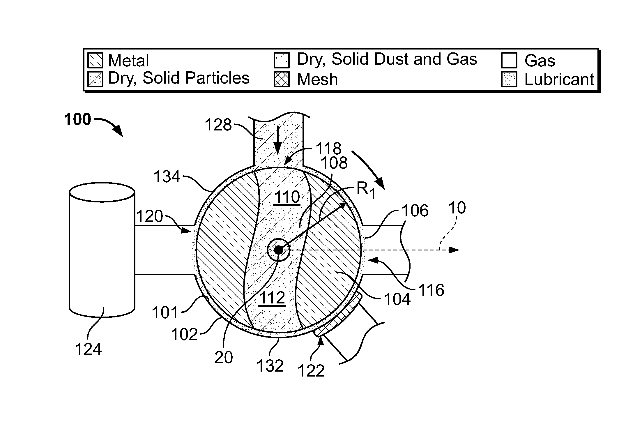
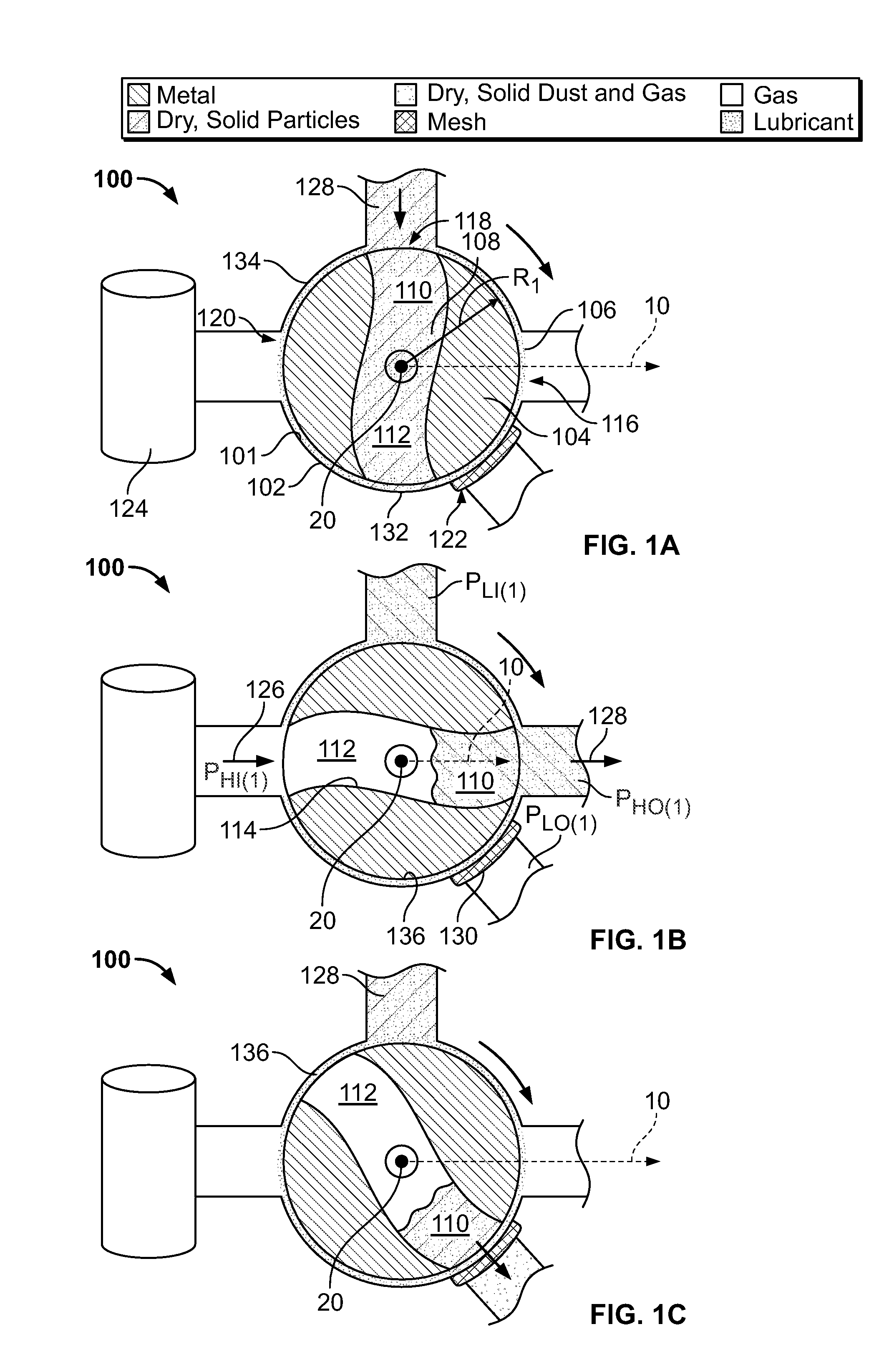
[0024]FIG. 1A is a schematic cross-sectional view of an exemplary rotary apparatus 100 at a first orientation, for example, but not limited to, a 90° orientation (also referred to herein as “orientation 1A”). FIG. 1B is a schematic cross-sectional view of rotary apparatus 100 in a second orientation, for example, but not limited to, a 0° orientation (also referred to herein as “orientation 1B”). FIG. 1C is a schematic cross-sectional view of rotary apparatus 100 in a third orientation, for example, but not limited to, a 315° orientation (also referred to herein as “orientation 1C”). Although orientations of rotary apparatus 100 are described as being at 90°, 0° and / or 315° from a reference direction 10, it should be understood that the values for the orientation degrees are exemplary only, are only illustrated for clarity of description, and are in no way limiting. For example, the components of rotary apparatus 100 may be oriented at any degree from reference direction 10 that enab...


PUM

PropertyMeasurementUnit
pressuresaaaaaaaaaa
pressuresaaaaaaaaaa
pressureaaaaaaaaaa

Abstract

A method for transporting a solid particulate within a gasifier system is provided. The method includes discharging solid particulate through an inlet into an opening defined within a rotor, wherein the inlet and the solid particulate are at a first pressure. The method further includes rotating the rotor such that at least one end of the opening is aligned in flow communication with a duct at a second pressure that is different from the first pressure. The solid particulate is discharged from the rotor opening through an outlet such that the solid particulate is at the second pressure, and the rotor is rotated such that at least one end of the rotor opening is aligned in flow communication with a pressure source that is at approximately the first pressure, and such that the opening is at the first pressure.

Description

BACKGROUND OF THE INVENTION[0001]This invention relates generally to a rotary apparatus for use with a gasifier system, and, more specifically, to a rotary apparatus for use in transporting a solid particulate within a gasifier system.[0002]Some known coal gasification systems use an entrained bed, non-catalytic, partial oxidation Texaco Gasification Process (TGP) in which carbonaceous feedstock reacts at elevated temperatures and pressures to produce synthetic gas that includes carbon monoxide and hydrogen. In at least some known gasification systems, carbonaceous feed, such as, high-rank bituminous coal, is first made into a slurry and is then pumped to a specially designed injector mounted at the top of the refractory-lined gasifier. As such, difficulties involved into feeding dry feedstock to the gasifier at high pressures are avoided. However, known slurry water may represent a thermal liability because the vaporization and heating of water increases oxygen consumption within t...

Claims


Application Information

Patent Timeline
Patent Type & Authority Applications(United States)
IPC IPC(8): C10J3/30
CPCB65G53/4633C10J3/30C10J3/34C10J2200/156C10J3/52C10J2200/15C10J3/50
Inventor KIM, JYUNG-HOONSTEVENSON, JOHN SAUNDERSRUSSELL, STEVEN CRAIGAVAGLIANO, AARON JOHN
Owner GENERAL ELECTRIC CO
Why Eureka
Try Eureka