Roofing Products Having Receptor Zones and Photovoltaic Roofing Elements and Systems Using Them

Inactive Publication Date: 2009-06-25
CERTAINTEED CORP
View PDF17 Cites 105 Cited by
  • Summary
  • Abstract
  • Description
  • Claims
  • Application Information

AI Technical Summary

Benefits of technology

[0024]The products, elements, systems, methods and kits of the present invention can result in a number of advantages. For example, in some embodiments, the products and systems of the present invention can provide enhanced adhesion between the photovoltaic element and the flexible roofing substrate. In other examples, the methods of the present invention can

Problems solved by technology

First, fossil fuels have become increasingly expensive due to increasing scarcity and unrest in areas rich in petroleum deposits.
Second, there exists overwhelming concern about the effects of the combustion of fossil fuels on the environment due to factors such as air pollution (from NOx, hydrocarbons and ozone) and global warming (from CO2).
However, in many circumstances, formation of a long-lived physical connection between the material of the encapsulated photovoltaic element and the material of a substrate can be difficult, especially when the materials used to make the encapsulated photovoltaic element have low surface tension.
Notably, the s

Method used


Image

  • Roofing Products Having Receptor Zones and Photovoltaic Roofing Elements and Systems Using Them
  • Roofing Products Having Receptor Zones and Photovoltaic Roofing Elements and Systems Using Them
  • Roofing Products Having Receptor Zones and Photovoltaic Roofing Elements and Systems Using Them

Examples


Embodiment Construction

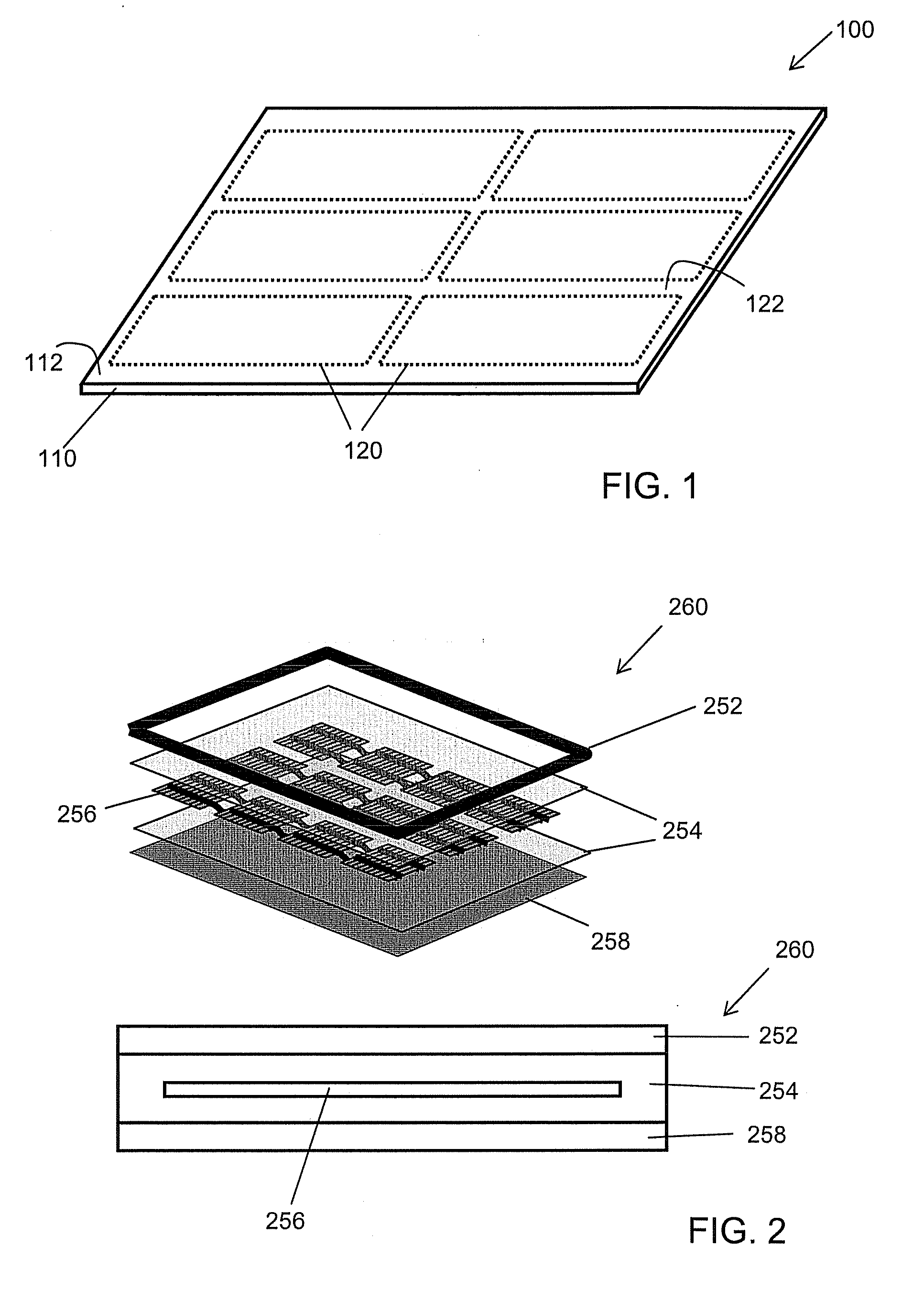
[0043]One embodiment of a roofing product according to the present invention is shown in schematic perspective view in FIG. 1. Roofing product 100 comprises a flexible roofing substrate 110 having a top surface 112. One or more (in this embodiment, six) receptor zones 120 are on the top surface 112 of flexible roofing substrate 110. Each receptor zone 120 is adapted to receive one or more photovoltaic elements, and has a different surfacing than the area 122 of the top surface adjacent to the receptor zone 120. The sizes and shapes of the one or more receptor zones can, for example, be selected based on the sizes and shapes of the photovoltaic elements envisioned for use therewith. For example, certain photovoltaic elements available from Uni-solar Ovonic have dimensions of about 12 cm×18 cm (T-Cells); about 24 cm×36 cm (L-Cells); or about 40 cm×5 m (strip).

[0044]In some embodiments, the receptor zone has dimensions that are somewhat larger than (e.g., in the range of 101-120% of, o...


PUM

PropertyMeasurementUnit
Flexibilityaaaaaaaaaa
Adhesivityaaaaaaaaaa
Areaaaaaaaaaaa

Abstract

The present invention relates generally to roofing products. The present invention relates more particularly to roofing products for use with photovoltaic elements, and to photovoltaic systems that include one or more photovoltaic elements is joined to a roofing substrate. In one embodiment, a roofing product includes a flexible roofing substrate having a top surface, the top surface having one or more receptor zones thereon, each receptor zone being adapted to receive one or more photovoltaic elements, each receptor zone having a different surfacing than the area of the top surface adjacent to it.

Description

CROSS-REFERENCE TO RELATED APPLICATIONS[0001]This application claims priority under 35 U.S.C. §119(e) to U.S. Provisional Patent Applications Ser. No. 61 / 014,902, filed Dec. 19, 2007; and Ser. No. 61 / 043,707, filed Apr. 9, 2008, each of which is hereby incorporated herein by reference in its entirety.BACKGROUND OF THE INVENTION[0002]1. Field of the Invention[0003]The present invention relates generally to roofing products. The present invention relates more particularly to roofing products for use with photovoltaic elements, and to photovoltaic systems that include one or more photovoltaic elements joined to a roofing substrate.[0004]2. Technical Background[0005]The search for alternative sources of energy has been motivated by at least two factors. First, fossil fuels have become increasingly expensive due to increasing scarcity and unrest in areas rich in petroleum deposits. Second, there exists overwhelming concern about the effects of the combustion of fossil fuels on the enviro...

Claims


Application Information

Patent Timeline
IPC IPC(8): H01L31/048E04D13/18E04C2/20E04B1/38
CPCE04D5/02Y02B10/12E04D13/00Y10T29/49826H02S20/23Y10T156/10H01L31/18Y02B10/10Y02E10/50
Inventor KALKANOGLU, HUSNU M.JACOBS, GREGORY F.SHAW, WAYNE E.CHIHLAS, PETER
Owner CERTAINTEED CORP
Why Eureka
Try Eureka