System and process for collecting effluents from an electrolytic cell

an electrolysis cell and effluent technology, applied in the direction of combustion process, dirt cleaning, combustion treatment, etc., can solve the problems of reducing the collection efficiency of the extraction system, complex system, and involving mechanical means, and significantly increasing the investment cos

Inactive Publication Date: 2009-06-25
ALUMINUM PECHINEY
View PDF8 Cites 48 Cited by
  • Summary
  • Abstract
  • Description
  • Claims
  • Application Information

AI Technical Summary

Benefits of technology

[0012]a second end that is located inside said at least one outlet channel, includes at least one aperture and is oriented so that pressurized air can be projected through said aperture in a manner that increases the rate of said flow of gas within said at least one outlet channel.
[0017]supplying pressurized air in said at least one pipe at a specified flow rate so as to increase the rate of said flow of gas within said at least one outlet channel.
[0019]Advantageously, the pressure and flow rate of the pressurized air in said pipe(s) is adjusted according to the actual suction needs. This embodiment of the invention enables tighter control on the needs for pressurized air supply.
[0020]The invention makes it possible to efficiently vary the rate of the flow of gas in the outlet channel(s) without requiring excessively large pressure or flow rates for the pressurized air. The invention avoids using mechanical parts within the flow of effluents coming out of the cell.

Problems solved by technology

However, the removal of hoods or the opening of access doors decreases the collection efficiency of the extraction system and lets some effluents escape into the surrounding atmosphere.
This system is complicated and includes mechanical means subject to the harsh conditions caused by the effluents.
Moreover, this solution significantly increases the investment cost because it requires separate duct networks.

Method used


Image

  • System and process for collecting effluents from an electrolytic cell
  • System and process for collecting effluents from an electrolytic cell
  • System and process for collecting effluents from an electrolytic cell

Examples


Embodiment Construction

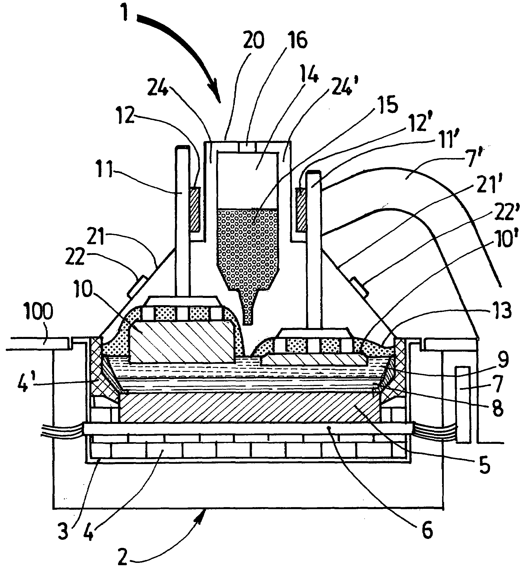
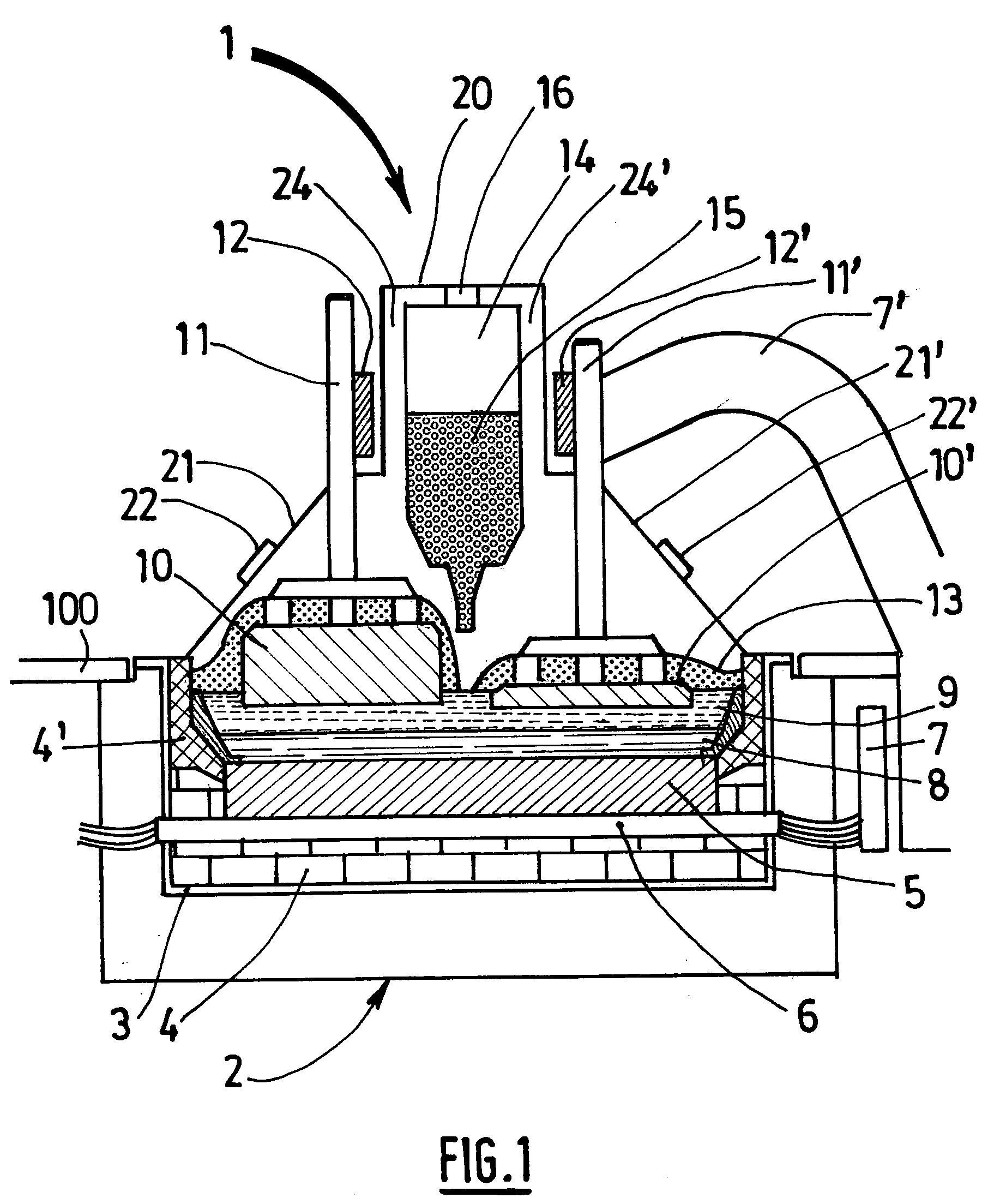
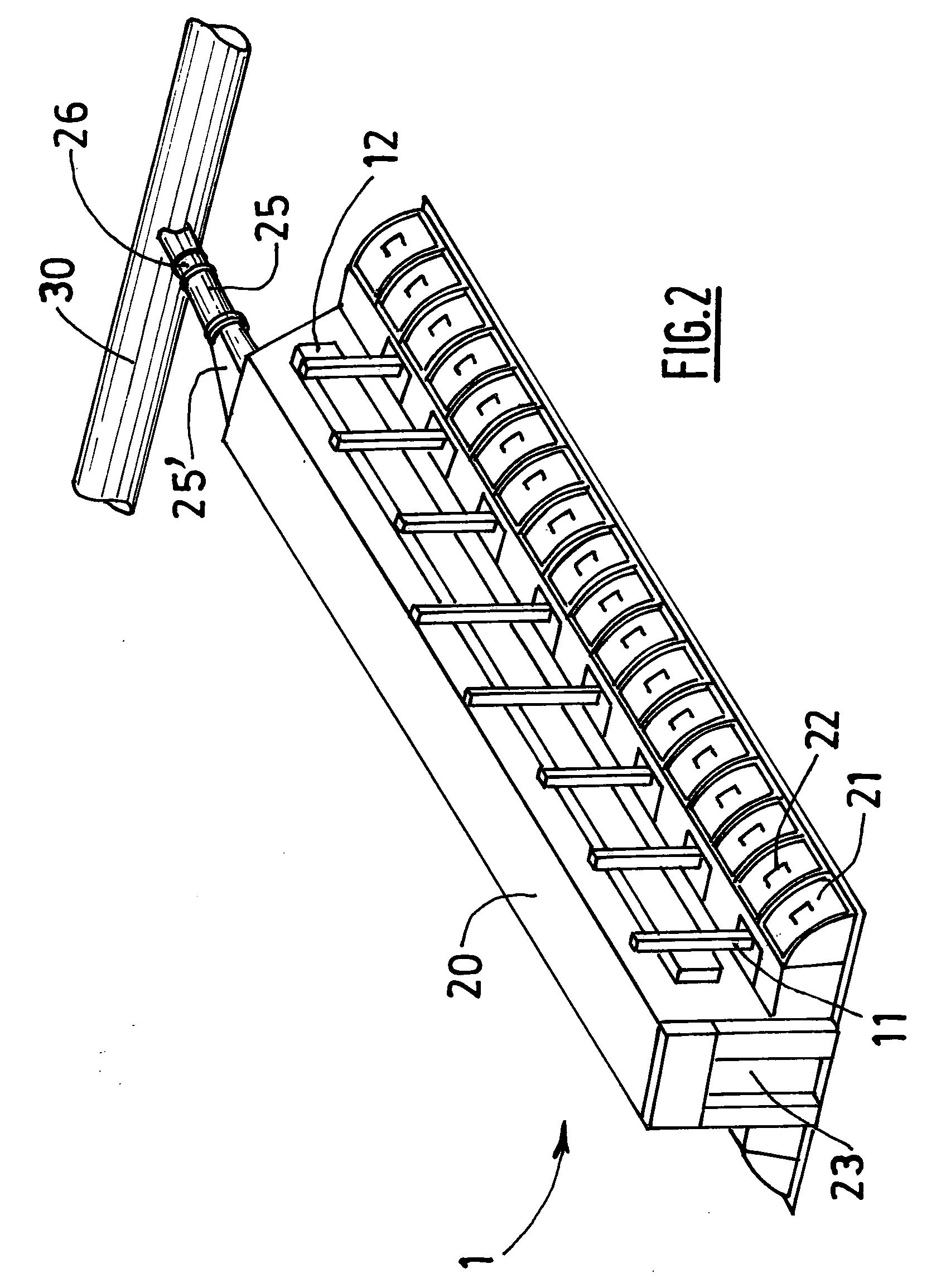
[0010]An object of the invention is a system for collecting effluents produced by an electrolytic cell intended for the production of aluminium and for drawing said effluents away from the cell in a flow of gas, said system comprising a hooding to confine the effluents, at least one outlet channel to collect said flow of gas and suction means to draw said flow of gas away from the cell through said at least one outlet channel, said hooding including removable hoods and, optionally, at least one door, to get access to the inside of the hooding, wherein said system further comprises at least one pipe comprising:[0011]a first end that is directly or indirectly connected to a pressurized air supply and[0012]a second end that is located inside said at least one outlet channel, includes at least one aperture and is oriented so that pressurized air can be projected through said aperture in a manner that increases the rate of said flow of gas within said at least one outlet channel.

[0013]An...


PUM

PropertyMeasurementUnit
pressureaaaaaaaaaa
pressureaaaaaaaaaa
pressureaaaaaaaaaa

Abstract

The invention provides a system and a process for collecting effluents produced by an electrolytic cell intended for the production of aluminium and for drawing said effluents away from the cell in a flow of gas. The system comprising a hooding to confine the effluents, at least one outlet channel to collect said flow of gas and suction means to draw said flow of gas away from the cell. The hooding includes removable hoods and, optionally, at least one door to get access to the inside of the hooding. The system further comprises at least one pipe for blowing pressurized air within the outlet channel so as to increase the rate of said flow of gas. Pressurized air supply is activated at a specified pressure Po so as to obtain a specified flow rate Ro.

Description

FIELD OF THE INVENTION[0001]The invention relates to the production of aluminium by igneous electrolysis. It more particularly relates to the extraction and treatment of airborne effluents produced by electrolytic cells designed for the production of aluminium.BACKGROUND ART[0002]Aluminium metal is produced industrially by igneous electrolysis, i.e. by electrolysis of alumina in solution in a molten cryolite bath using the well-known Hall-Héroult process. A plant for the production of aluminium comprises a plurality of electrolytic cells, typically several hundreds, which are arranged in rows and connected in series. U.S. Pat. No. 6,409,894 in the name of Aluminium Pechiney describes possible arrangements of plants intended for the production of aluminium using electrolytic cells.[0003]Electrolytic reactions, secondary reactions and high operating temperatures lead to the production of airborne effluents that, in particular, contain carbon dioxide, fluorinated products and dust (alu...

Claims


Application Information

Patent Timeline
Patent Type & Authority Applications(United States)
IPC IPC(8): C25C3/22C25B15/02
CPCB08B15/002F23L17/16F23J11/02C25C3/22
Inventor GIRAULT, GUILLAUMECANTIN, PHILIPPE
Owner ALUMINUM PECHINEY
Why Eureka
Try Eureka