
Motor assembly incorporating a securely positioned electromagnetic disturubance suppression device

Inactive Publication Date: 2009-06-25
CALSONICKANSEI NORTH AMERICA
View PDF5 Cites 16 Cited by
  • Summary
  • Abstract
  • Description
  • Claims
  • Application Information

AI Technical Summary

Benefits of technology

[0006]Accordingly, it is an advantage of the present invention that a motor assembly is provided having an electromagnetic disturbance (EMD) suppression chip device for electromagnetic disturbance suppression.
[0007]It is another advantage of the present invention that a motor assembly is provided having an EMD suppression chip device that is securely positioned within an end cap of the motor assembly.
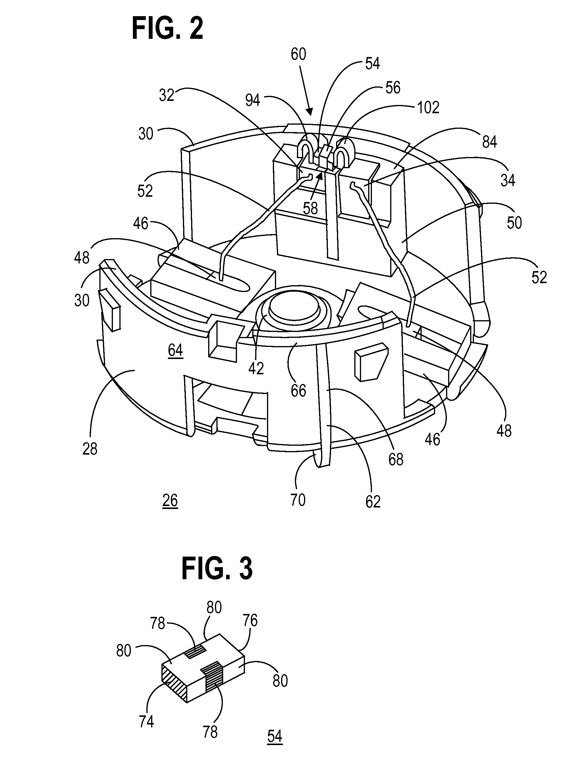
[0008]The above and other advantages of the present invention are carried out in one form by a motor assembly comprising a motor having a conductive housing and an end cap coupled to the motor. The end cap includes a body formed from insulating material, the body having a peripheral edge that interfaces with the conductive housing. A first motor terminal and a second motor terminal are located in the body. An electromagnetic disturbance (EMD) suppression chip device is located in the body. The EMD suppression chip device has a first input terminal, a second input terminal, and an earth terminal. The first input terminal is in electrical communication with the first motor terminal, and the second input terminal is in electrical communication with the second motor terminal. A conductive ground strap is in electrical communication with the earth terminal. The conductive ground strap has a first end retaining the chip device in the end cap and a second end fitted onto the peripheral edge of the end cap between the end cap and the conductive housing of the motor.

Problems solved by technology

Electric motors are a significant source of radiated and conducted electromagnetic emissions, referred to herein as electromagnetic disturbance (EMD), which can degrade the performance of a device, equipment, or system.
However, as packaging space becomes more limited, it has become increasingly difficult to package these components within the motor housing.
A problem associated with the incorporation of an EMD suppression chip device into a motor assembly is that of securing the EMD suppression chip device, especially in a high vibration environment.
For example, when the motor assembly is in a vehicle, the motion and vibration of the vehicle can cause the EMD suppression chip device to move or vibrate out of contact with one or both motor terminals and / or the ground path.
Of course, should the EMD suppression chip device become disconnected from the motor terminals and / or the ground path, its ability to suppress noise generated by the motor is severely compromised.

Method used


Image

  • Motor assembly incorporating a securely positioned electromagnetic disturubance suppression device
  • Motor assembly incorporating a securely positioned electromagnetic disturubance suppression device
  • Motor assembly incorporating a securely positioned electromagnetic disturubance suppression device

Examples


Embodiment Construction

[0018]The present invention entails a motor assembly having electromagnetic disturbance (EMD) suppression. EMD may be radiated and conducted as known to those skilled in the art. The motor assembly can be utilized in a multiplicity of applications and environments, but is particularly suited for use in a high movement or vibration environment, such as in a vehicle.

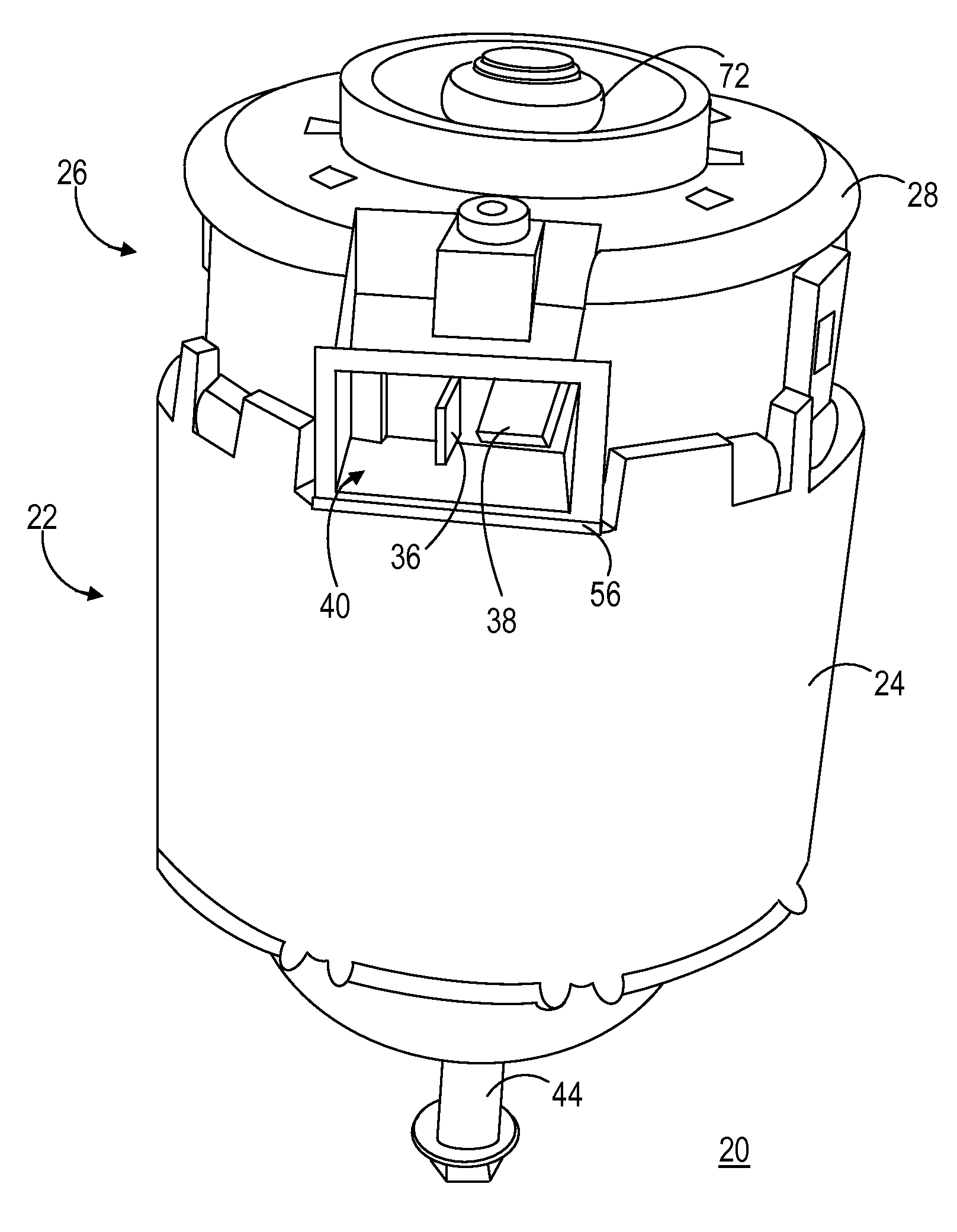
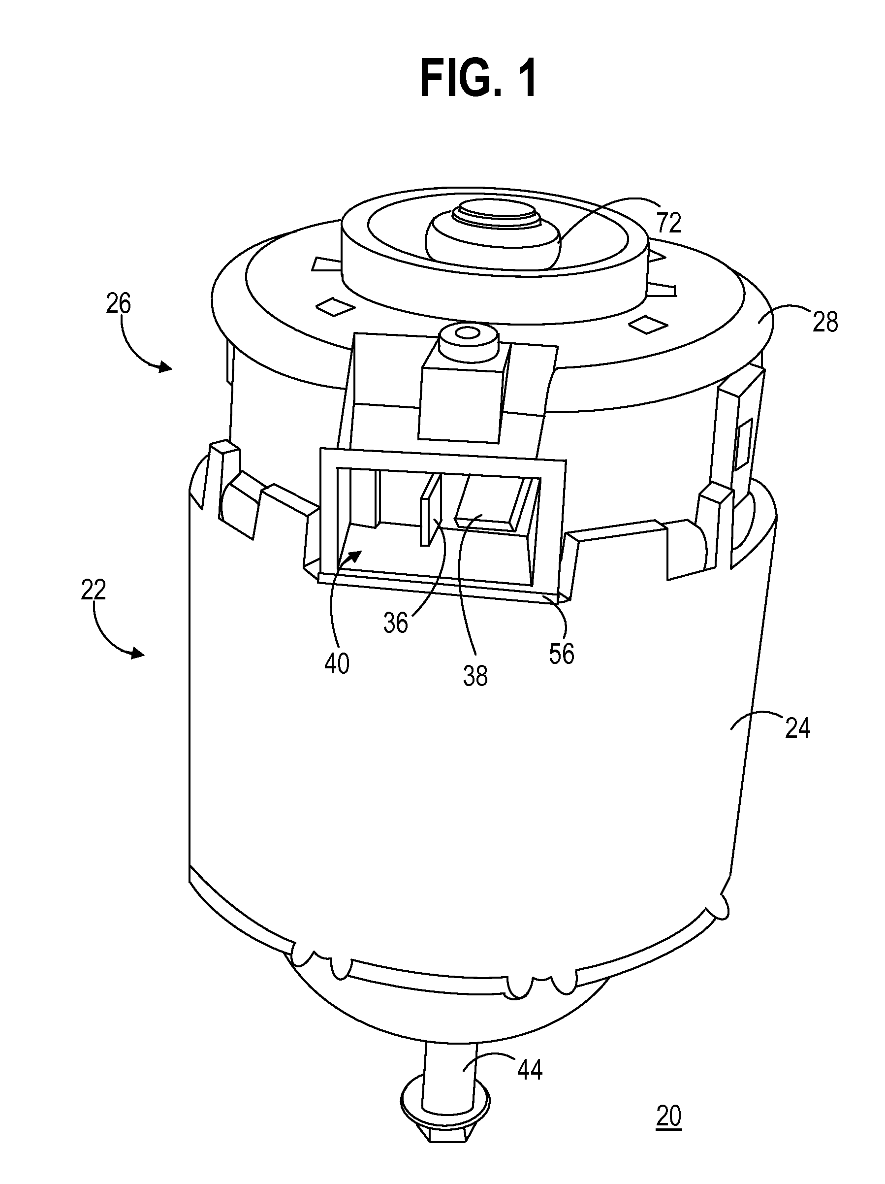
[0019]FIG. 1 shows a perspective view of a motor assembly 20 in accordance with the present invention. Motor assembly 20 includes a motor 22 having an electrically conductive housing 24 and an end cap 26 coupled to motor 22. End cap 26 includes a body 28 having a peripheral edge 30 (best seen in FIG. 2) that interfaces with conductive housing 24 of motor 22. Motor 22 may be a direct current (DC) brush type blower motor for a vehicle. However, it should be understood that motor 22 may alternatively be any of a number of motors, such as, but not limited to, a motor for operating windshield wipers, electric windows, sunroofs,...


PUM


Abstract

A motor assembly (20) includes a motor (22) and an end cap (26). The end cap (26) includes an electrically insulating body (28) having a peripheral edge (30) that interfaces with a conductive housing (24) of the motor (22). Motor terminals (94, 102) and an electromagnetic suppression (EMD) chip device (54) are located within the body (28). The chip device (54) has an input terminal (74) in electrical communication with the motor terminal (94), an input terminal (76) in electrical communication with the motor terminal (102), and an earth terminal (78). A conductive ground strap (56) is in electrical communication with the earth terminal (78). The ground strap (56) encapsulates and retains the chip device (54) in the end cap (26) and has an end (60) fitted onto the peripheral edge (30) of the end cap (26) between the end cap (26) and the conductive housing (24) of the motor (22).

Description

TECHNICAL FIELD OF THE INVENTION[0001]The present invention relates to the field of electric motors. More specifically, the present invention relates to electric motors having reduced electromagnetic disturbance characteristics.BACKGROUND OF THE INVENTION[0002]Electric motors are a significant source of radiated and conducted electromagnetic emissions, referred to herein as electromagnetic disturbance (EMD), which can degrade the performance of a device, equipment, or system. EMD can be radiated and conducted through electrical lines from sources such as the motor, electronic devices, and the like. Controlling conducted and radiated emissions produced by different electrical and electronic devices, including electric motors, is critical for protecting electronic equipment in the surrounding environment.[0003]Many electric motor assemblies include EMD suppression components such as capacitors and inductors mounted within the motor itself. However, as packaging space becomes more limi...

Claims


Application Information

Patent Timeline
IPC IPC(8): H02K5/24H02K11/00H01R13/648
CPCH01R4/4809H01R13/65802H01R13/6608H02K11/026H02K5/225H02K11/0005H02K11/0089H01R2201/26H01R13/6583H02K11/40
Inventor RAGNONE, ROCCOROZENBERG, ARONLIGHTFOOT, DAVIDJOHNSON, LAWRENCE
Owner CALSONICKANSEI NORTH AMERICA
Learn More