Hybrid permanent magnet motor

a permanent magnet motor and hybrid technology, applied in the direction of motor/generator/converter stopper, dynamo-electric converter control, instruments, etc., can solve the problems of reducing the efficiency of operation when the motor is producing peak power, introducing high cogging torque at start-up, and unable to turn off permanent magnets, etc., to achieve low cogging force, high efficiency, and high power density

Active Publication Date: 2009-06-25
QM POWER
View PDF25 Cites 43 Cited by
  • Summary
  • Abstract
  • Description
  • Claims
  • Application Information

AI Technical Summary

Benefits of technology

[0005]This disclosure relates to a permanent magnet electro-mechanical device that functions as a motor or generator that uses control coils, a shaft mounted salient pole rotor, bearings and structural components and a novel arrangement of two or more permanent magnets placed in the stator portion. This construction exhibits low cogging forces, high efficiency and high power density. The rotor and stator pole geometries and spacing relationships can be arranged to operate as either a single phase or multi phase motor.

Problems solved by technology

Replacing coils with permanent magnets introduced a new motor design challenge.
The field of the permanent magnets cannot be ‘turned off,’ which introduces high cogging torques at start-up.
The constant magnetic flux also causes the motor's back electromotive force to become linear with speed, resulting in a linear speed to torque relationship, which reduces the efficiency of operation when the motor is producing peak power.
This electronic control approach works well for modifying the linear speed to torque relation to produce a more hyperbolic speed to torque relationship, but requires increasing the size and ultimately the weight of the controlled motor.

Method used


Image

  • Hybrid permanent magnet motor
  • Hybrid permanent magnet motor
  • Hybrid permanent magnet motor

Examples


Embodiment Construction

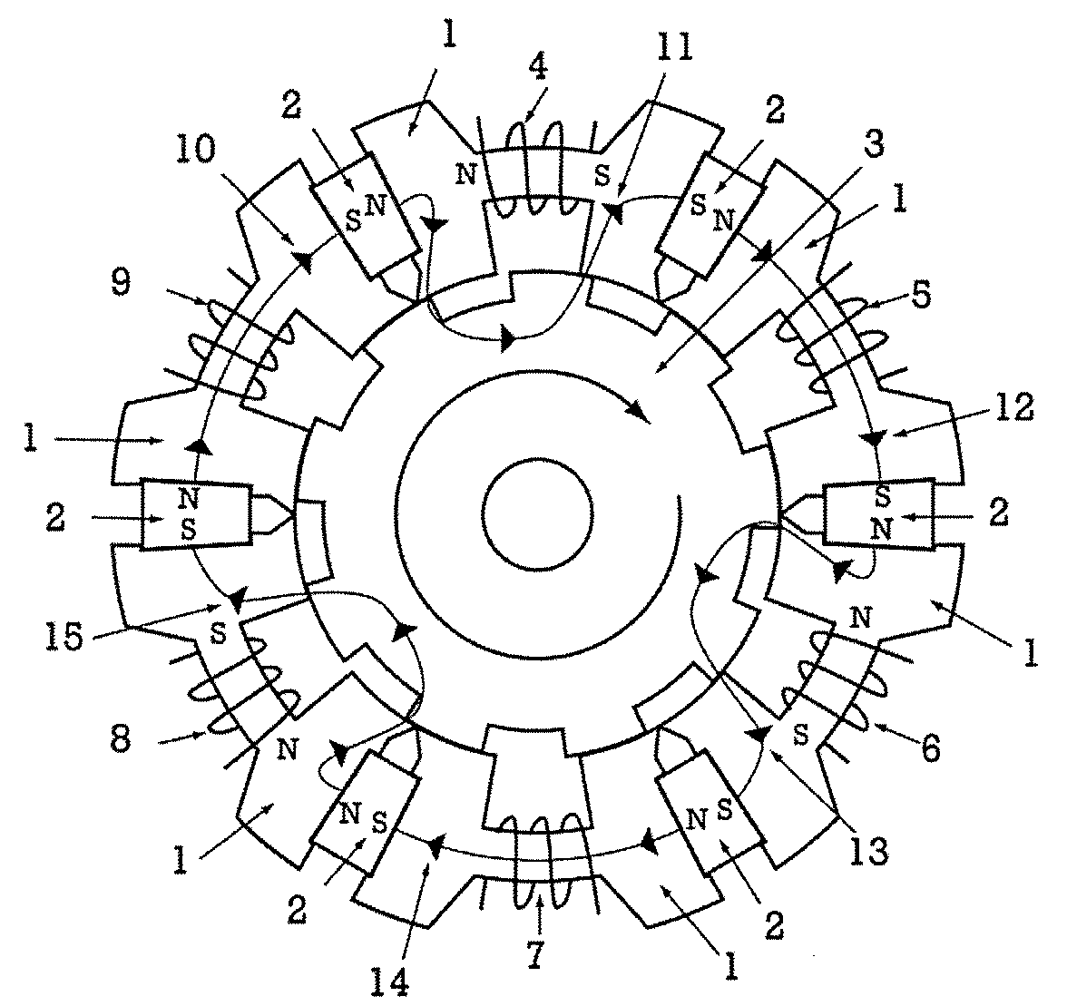
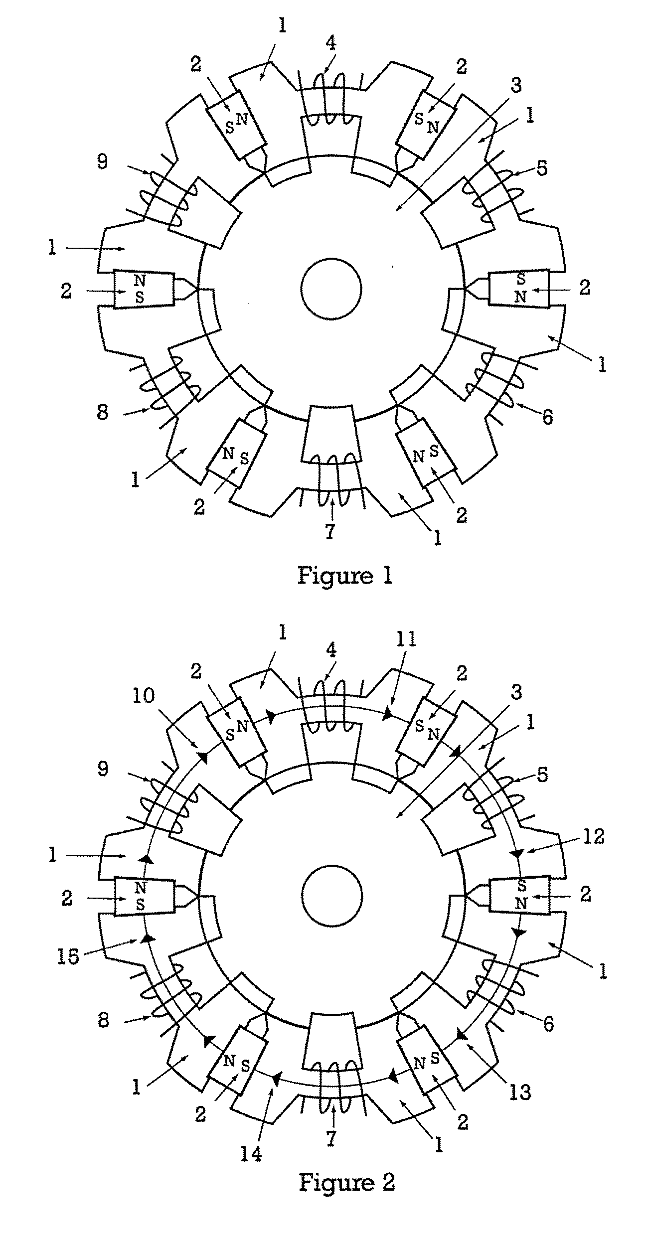
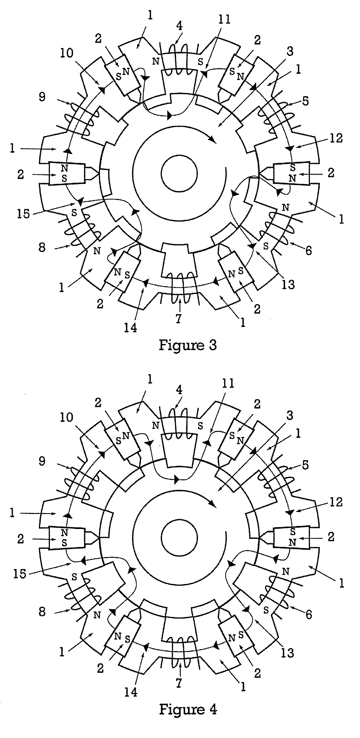
[0023]An apparatus, method and means for providing a permanent magnet electro-mechanical device that functions as a motor or generator are disclosed. The permanent magnets in the electro-mechanical device are arranged in the stator in an attracting manner. This can provide a one hundred percent field weakening when no current is flowing in the phase windings and allow control of the electro-mechanical device through the phase windings. The arrangement additionally provides low to no cogging torque or back electromotive force because the magnetic flux of the permanent magnets generally does not act across the air gap between the rotor and stator. A small amount of fringing flux may be present in device operation, but this does not produce the back electromotive force that is present in typical permanent magnet motors. The arrangement of magnets and phase windings also provides high efficiency operation of the electro-mechanical device by allowing phase winding flux to be applied in c...


PUM


Abstract

An electro-mechanical device that functions as a motor or a generator and methods for constructing and using such electro-mechanical device are provided. The electro-mechanical device features permanent magnets placed in a magnetically attracting manner and inter-dispersed between control coils. The control coils are energized to create a flux opposing the flux of the permanent magnets and to create a rotational torque on the poles of a salient pole rotor before those poles align with the poles of the energized control coil stator segment. Power can be generated by placing the flux of the control coils in a steady state and mechanically rotating the salient pole rotor. The electro-mechanical device provides little or no cogging forces, high-efficiency operation, and a high power density.

Description

CROSS-REFERENCE TO RELATED APPLICATION[0001]This application claims benefit under 35 U.S.C. § 119(e) of U.S. Provisional Patent Application No. 60 / 893,496, entitled “Hybrid Permanent Magnet Motor,” filed Mar. 7, 2007, which is hereby incorporated by reference herein in its entirety.TECHNICAL FIELD OF THE DISCLOSURE[0002]Apparatus and methods for providing a permanent magnet electro-mechanical device that functions as a motor or generator are disclosed.BACKGROUND OF THE DISCLOSURE[0003]With few exceptions the basic operating principles for electric motors and generators have not changed much over the past 100 years. With the development of high energy or high coercive force permanent magnets the power density and efficiency of electric motors was increased over the then state of the art motor technologies by replacing the field coils in brush motors or armature coils in brush-less motors with permanent magnets. The permanent magnets require less space and typically weigh less than th...

Claims


Application Information

Patent Timeline
Patent Type & Authority Applications(United States)
IPC IPC(8): H02P6/00H02K37/04
CPCH02K21/44H02K19/103
Inventor FLYNN, CHARLES J.
Owner QM POWER
Why Eureka
Try Eureka