Power Supply for a Load Control Device

a technology of load control device and power supply, which is applied in the direction of electric variable regulation, process and machine control, instruments, etc., can solve the problems that the semiconductor cannot be turned on for the entire length of a half-cycle, and the lighting load may generate acoustic nois

Active Publication Date: 2009-06-25
LUTRON TECH CO LLC
View PDF40 Cites 29 Cited by
  • Summary
  • Abstract
  • Description
  • Claims
  • Application Information

AI Technical Summary

Problems solved by technology

Thus, the semiconductor cannot be turned on for the entire length of a half-cycle, even when the maximum voltage across the lighting load is desired.
If the electrical load is sensitive to asymmetrical currents, such as a magnetic low-voltage (MLV) lighting load, the lighting load may generate acoustic noise, which is undesirable.

Method used


Image

  • Power Supply for a Load Control Device
  • Power Supply for a Load Control Device
  • Power Supply for a Load Control Device

Examples


Embodiment Construction

[0030]The foregoing summary, as well as the following detailed description of the preferred embodiments, is better understood when read in conjunction with the appended drawings. For the purposes of illustrating the invention, there is shown in the drawings an embodiment that is presently preferred, in which like numerals represent similar parts throughout the several views of the drawings, it being understood, however, that the invention is not limited to the specific methods and instrumentalities disclosed.

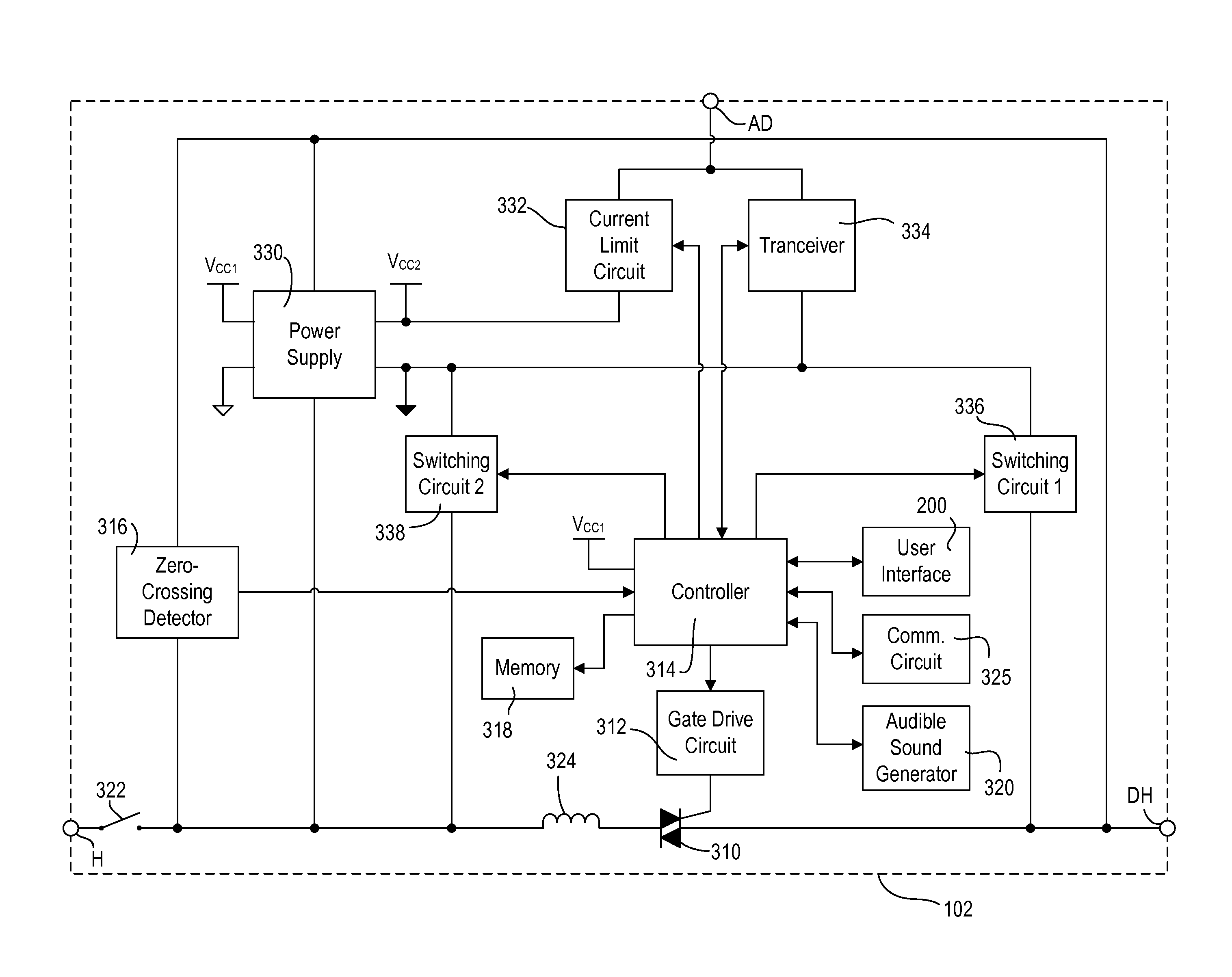
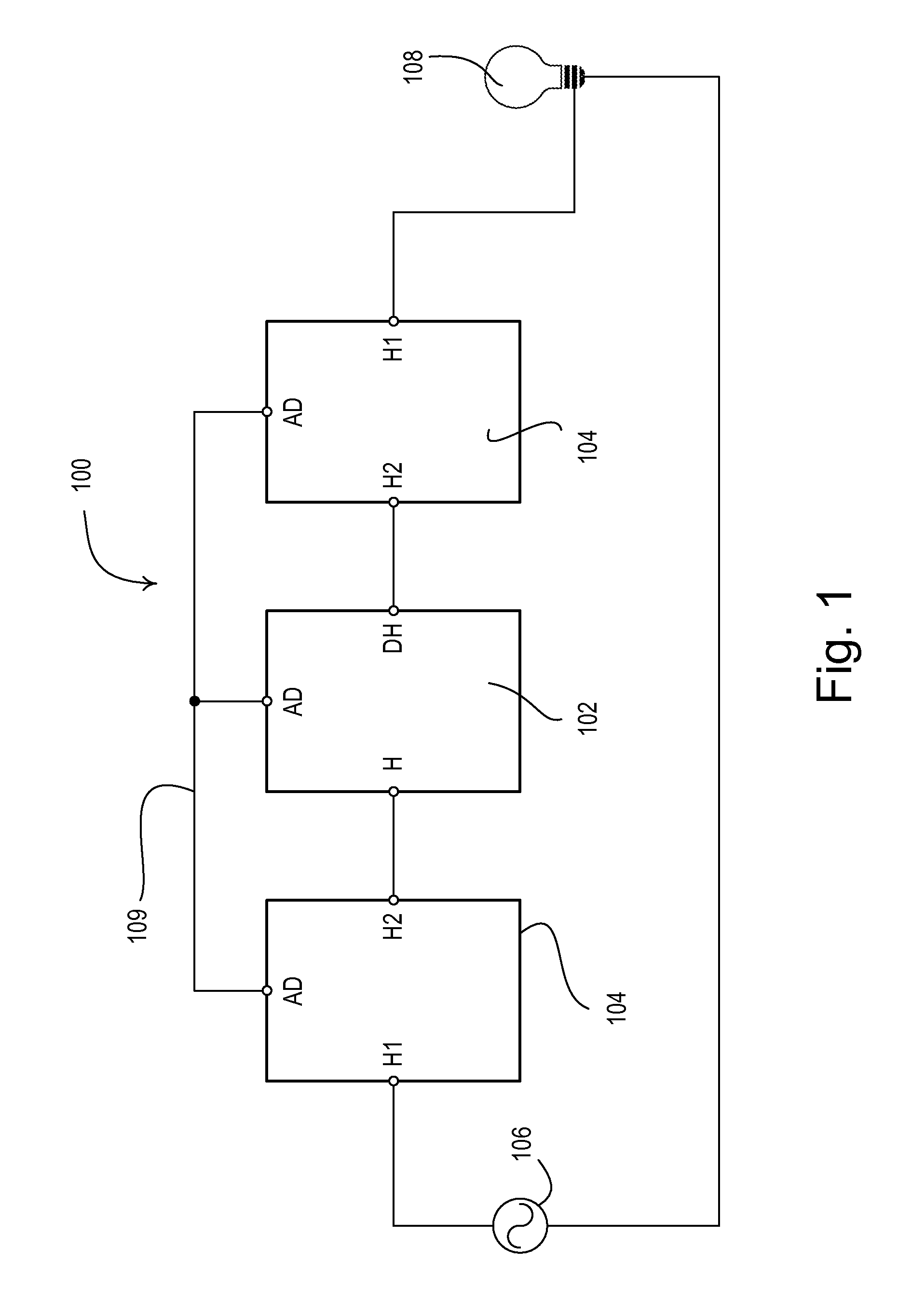
[0031]FIG. 1 is a simplified block diagram of a multiple location dimming system 100. As shown in FIG. 1, a main dimmer 102 and two remote dimmers 104 (i.e., accessory dimmers) are coupled in series electrical connection between an AC power source 106 and a lighting load 108. The main dimmer 102 includes a hot terminal H (i.e., a line-side load terminal) adapted to be coupled to the line-side of the system 100 and a dimmed-hot terminal DH (i.e., a load-side terminal) adapted to ...


PUM


Abstract

A power supply for a load control device generates a DC voltage and provides an asymmetrical output current, while drawing a substantially symmetrical input current. The power supply comprises a controllably conductive switching circuit for controllably charging an energy storage capacitor across which the DC voltage is produced. The energy storage capacitor begins charging at the beginning of a half-cycle and stops charging after a charging time in response to the magnitude of the DC voltage and the amount of time that the energy storage capacitor has been charging during the present half-cycle. The charging time is maintained substantially constant from one half-cycle to the next. The power supply is particularly beneficial for preventing asymmetrical current from flowing in a multiple location load control system having a master load control device supplying power to a plurality of remote load control devices all located on either the line-side or the load-side of the system.

Description

RELATED APPLICATIONS [0001]This application claims priority from commonly-assigned U.S. Provisional Application Ser. No. 61 / 015,965, filed Dec. 21, 2007, entitled POWER SUPPLY FOR A LOAD CONTROL DEVICE, the entire disclosure of which is hereby incorporated by reference.BACKGROUND OF THE INVENTION [0002]1. Field of the Invention[0003]The present invention relates to a power supply for a load control device, and more particularly, to a power supply for a load control device of a multiple location load control system, where the power supply draws a substantially symmetrical current, while powering an electrical load drawing an asymmetrical current.[0004]2. Description of the Related Art[0005]A conventional two-wire dimmer has two connections: a “hot” connection to an alternating-current (AC) power supply and a “dimmed hot” connection to the lighting load. Standard dimmers use one or more semiconductor switches, such as triacs or field effect transistors (FETs), to control the current d...

Claims


Application Information

Patent Timeline
Patent Type & Authority Applications(United States)
IPC IPC(8): H02J7/04
CPCH02M5/257H05B39/044H05B37/0263H02M2001/0006H05B47/185H02M1/0006Y02B20/00
Inventor CARMEN, DANIEL F.
Owner LUTRON TECH CO LLC
Why Eureka
Try Eureka