Drive circuit and electro-luminescent display system

a technology of drive circuit and display system, applied in the direction of electric digital data processing, instruments, computing, etc., can solve the problems of limiting the update rate of data, affecting the accuracy of data, and requiring a large display and switching element to be updated quite fas

Active Publication Date: 2009-06-25
GLOBAL OLED TECH
View PDF19 Cites 26 Cited by
  • Summary
  • Abstract
  • Description
  • Claims
  • Application Information

AI Technical Summary

Problems solved by technology

Unfortunately, the disadvantage of such a system is that the update rate of the display and the switching element must be quite high to avoid the perception of flicker.
Unfortunately, refresh rates significantly higher than 60 Hz can be difficult to attain in large active matrix thin-film electro-luminescent displays, such as OLED displays.
This capacitance can create a significant RC constant and limit the update rate at which data may be clocked into pixel circuits to rates below 120 Hz, particularly in larger displays where the resistance of the data lines can be significant.
Further, this prior art circuit has a large number of additional transistors and connecting wires, which complicate the circuit; uses large amounts of backplane real estate (limiting display resolution); and will require very high yield rates to allow successful manufacturing of a working active circuit.
Therefore, this particular prior art circuit is relatively large and can be expensive to implement.
Further, the circuit does not provide a method for reducing flicker as the image update, delayed by the display, is restricted to the same update rate.
However, as the handedness of the polarization of the light is kept constant during display of stereoscopic imagery, the resolution is reduced due to the fact that each eye can only see half of the columns of the display while viewing stereoscopic imagery.
However, when the display is not updated temporally, the effective resolution of the display is reduced; and when it is updated temporally, high update rates are required.
Unfortunately, the EL display would require a high refresh rate; and because the barrier screen is switched for an entire column, such a barrier would generally not be synchronized with pixel updates within an active matrix EL display.
While this latter patent recognizes that the update rate may be limited, it does not provide methods for increasing the effective refresh rate of the display.
However, the refresh rate (i.e., the number of frames provided each second) is limited by the capacitance and resistance of the display structure as it is limited for the analog drive methods and has the additional constraint that data for multiple subfields must be provided within each frame.

Method used


Image

  • Drive circuit and electro-luminescent display system
  • Drive circuit and electro-luminescent display system
  • Drive circuit and electro-luminescent display system

Examples


Embodiment Construction

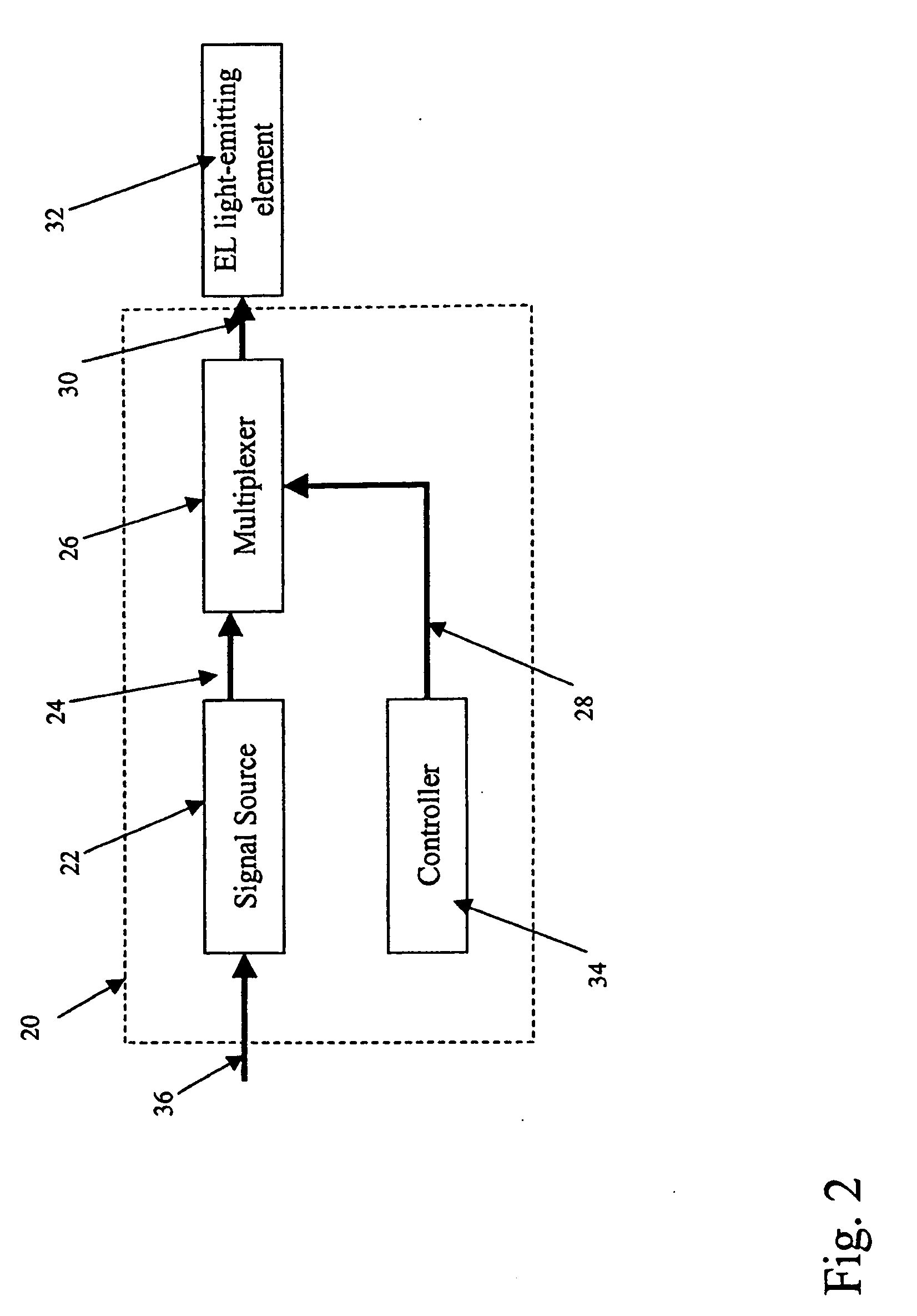
[0026]The aforementioned need is met by providing a drive circuit for rapidly interleaving image data displayed on an EL device as shown in FIG. 2. As shown, the drive circuit 20 is comprised of a signal source 22 that provides a plurality of image data signals 24, each image data signal being provided for a specified load period; a multiplexer 26 for receiving the plurality of image data signals 24, and in response to a selection signal 28, selecting one of the image data signals as a control signal 30 that directs the EL device to emit light 32; and a controller 34 causing interleaving of the image data signals 24 during multiple display periods by providing the selection signal 28 to the multiplexor 26; wherein each display period is shorter than the load period. As shown, the drive circuit provides a succession of values of the selection signal 28 to the multiplexer 26. Each selection signal 28 value will typically be provided for one display period. Typically, this drive circui...


PUM


Abstract

A drive circuit for rapidly interleaving image data displayed on an EL device is disclosed. The drive circuit includes a signal source that provides a image data signals. Each image data signal is provided for a specified load period. A multiplexer receives the image data signals, and in response to a selection signal selects one of the image data signals to provide a control signal that directs the EL device to emit light. Additionally, a controller causes interleaving of the image data during multiple display periods; each display period is shorter than the load period.

Description

FIELD OF THE INVENTION[0001]The present invention relates to a drive circuit and electro-luminescent display system. Particularly, the present invention includes a circuit and an electro-luminescent display for providing synchronous display of multiple signal values with a reduced update rate.BACKGROUND OF THE INVENTION[0002]Many display devices exist within the market today. Among the displays that are available are thin-film, coated, electro-luminescent displays, such as OLED displays. These displays may be driven using active matrix backplanes, which employ an active circuit.[0003]Stereoscopic displays are also known in the art. These displays may be formed using a number of techniques. Among the most commercially successful stereoscopic displays to date have been displays either employing some method of shuttering light, such that the light from one frame of data is able to enter only the left or right eye at any point in time and left and right eye images are shown in rapid suc...

Claims


Application Information

Patent Timeline
Patent Type & Authority Applications(United States)
IPC IPC(8): G09G5/00G09G3/30
CPCG09G3/3291G09G2300/0804G09G2300/0852H04N13/0497G09G2310/0275G09G2310/0297G09G2360/18G09G2310/0262H04N13/398
Inventor MILLER, MICHAEL E.WHITE, CHRISTOPHER J.
Owner GLOBAL OLED TECH
Why Eureka
Try Eureka