
Labelling Machine

a labeling machine and label technology, applied in the field of labeling machines, can solve the problems of additional uneconomical downtime, ink in the print head may dry up when the print head is pressed, etc., and achieve the effect of minimizing the amount of ink consumed

Inactive Publication Date: 2009-06-25
KRONES AG
View PDF5 Cites 17 Cited by
  • Summary
  • Abstract
  • Description
  • Claims
  • Application Information

AI Technical Summary

Benefits of technology

[0005]It is therefore the object of the present disclosure to provide an economical labelling machine in the case of which printing can be continued immediately and reliably after a time of nonuse or a malfunction of the labelling machine.
[0007]Hence, the discharge of ink can be continued even during a printing pause. A standstill of the ink and a resultant drying up of the ink is avoided in this way.
[0008]It will be advantageous when the ink jet printer is a demand-dependent printer. This allows the labelling machine to be operated at a particularly low cost.
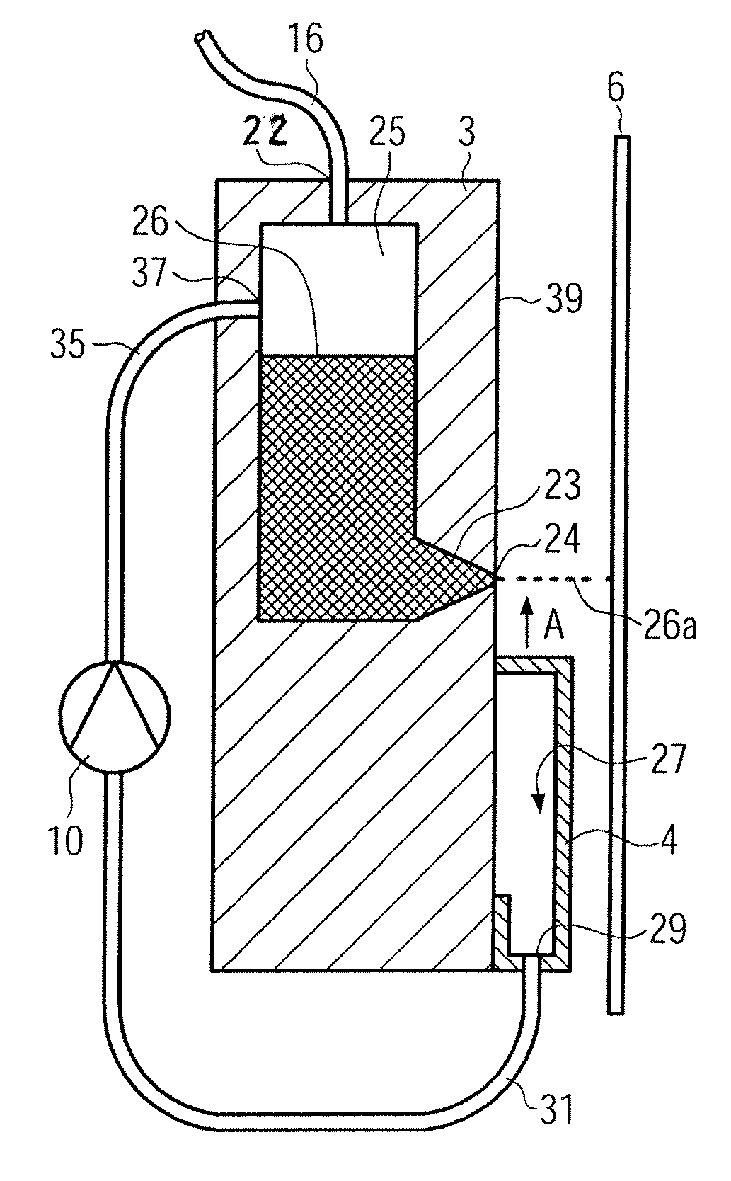
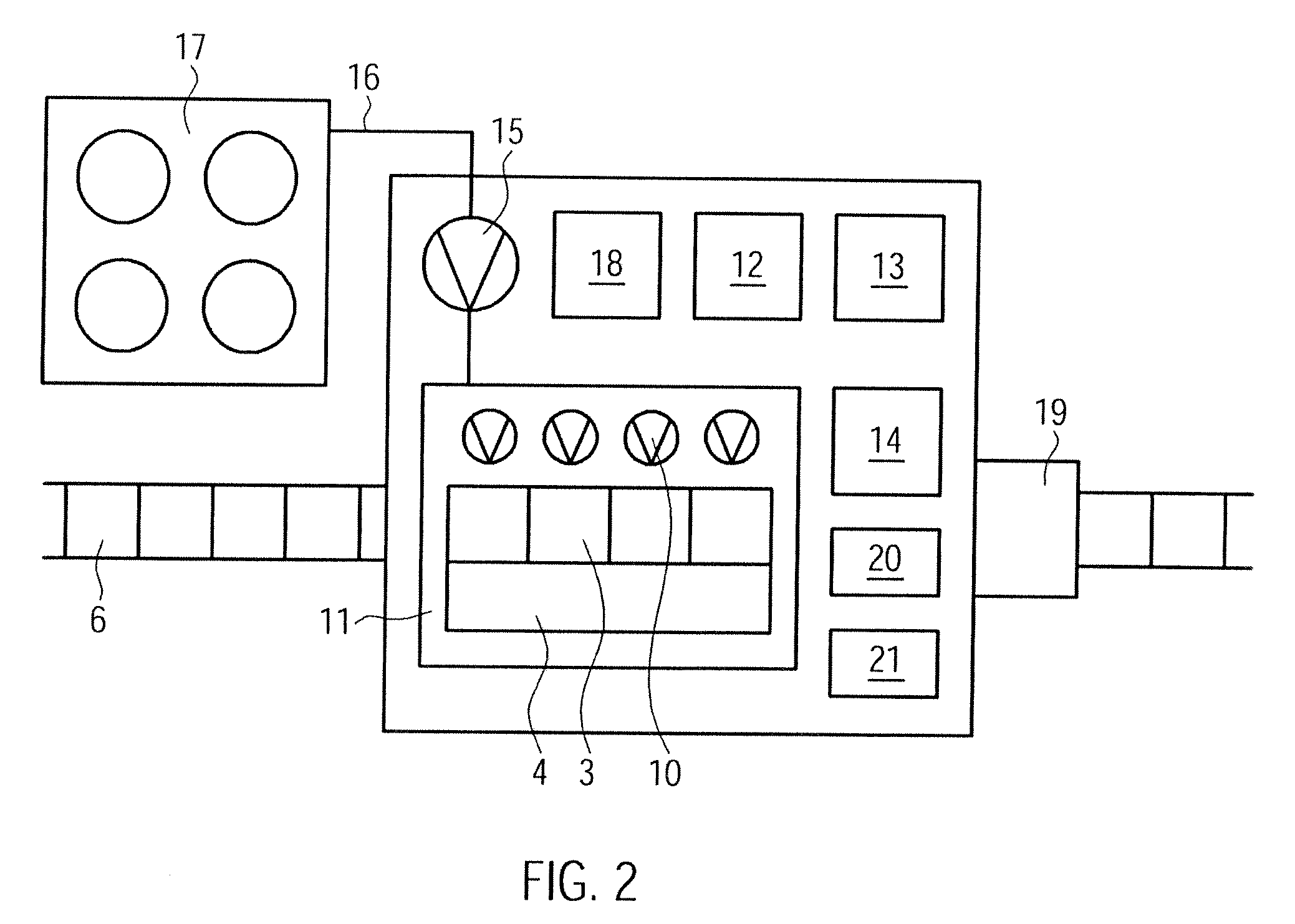
[0010]It is thus possible to recover inks from a plurality of print heads with the aid of a common cover and without an undesirable mixing of the individual colours.
[0011]According to an advantageous embodiment, the direction of the ink jet can remain unchanged when the cover is inserted. The amount of ink consumed can be minimized in this way.

Problems solved by technology

A problem which is characteristic of demand-dependent printers is, however, that the ink in the print head may dry up when the print head is not in use, e.g. when the labelling machine stands still due to a change of shifts or due to some malfunction.
Malfunctions may also be caused by a machine which is located upstream or downstream of a labelling machine incorporated in a line.
The cleaning or the exchange of the dried-up print head leads to an additional uneconomical downtime.

Method used


Image

  • Labelling Machine
  • Labelling Machine
  • Labelling Machine

Examples


Embodiment Construction

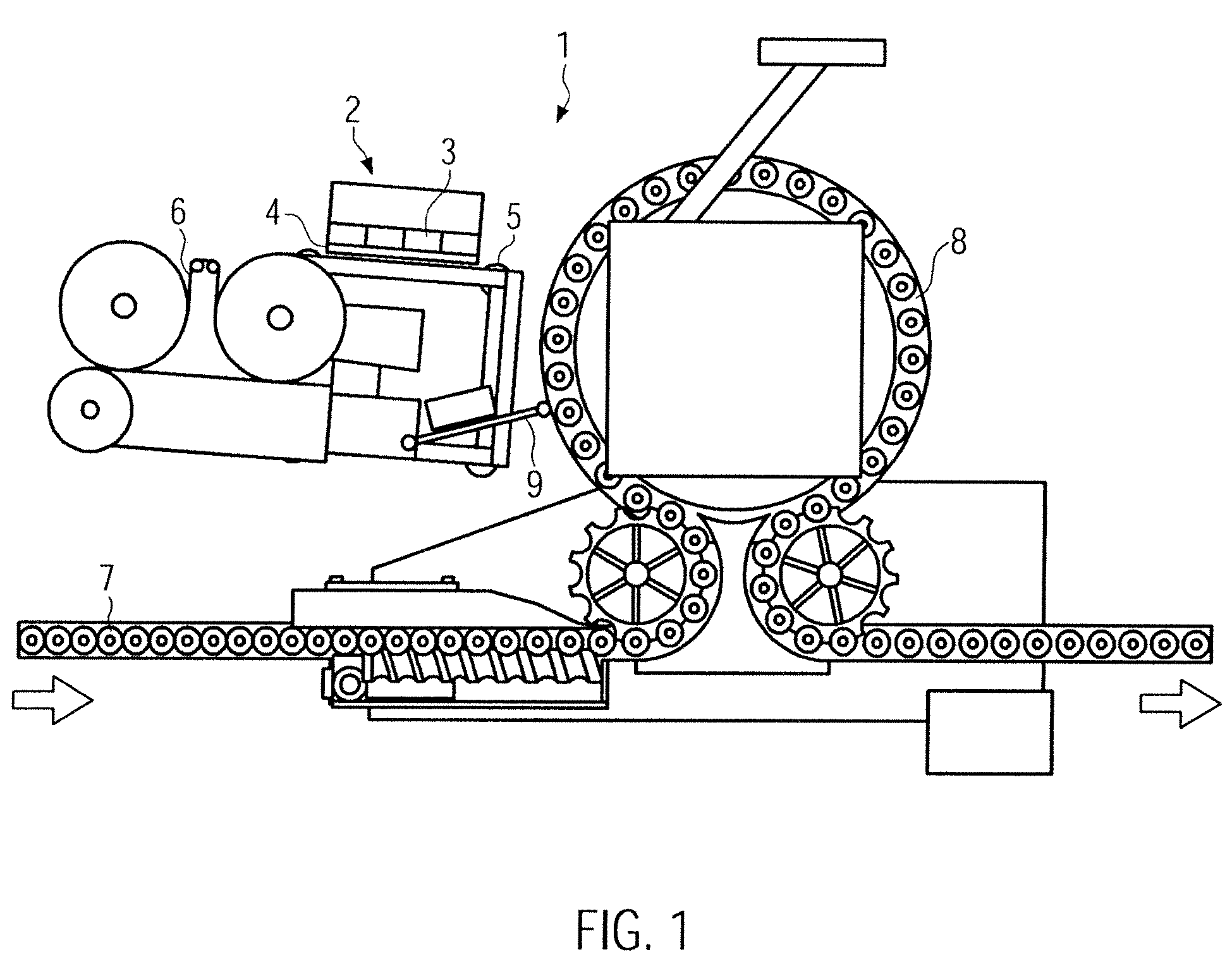
[0018]The modular labelling machine 1 shown in FIG. 1 comprises, in addition to the known basic construction, an ink jet printer 2 provided with one or a plurality of, e.g. four print heads 3 and a cover 4 which is movable to a position between the print heads 3 and a strip of labels 6 guided across the rolls 5.

[0019]In the example shown, the labelling machine 1 is configured as a rotary labeller, but it may also be configured as an inline labeller. As can be seen from FIG. 1, the containers 7 are fed via a bottle table 8 and labelled with the aid of a dispenser unit 9. It is, however, also possible to configure the labelling machine I for direct printing. In this case, the containers 7, instead of the strip of labels 6, are positioned in front of the print heads 3, i.e. the print heads are then oriented such that they face the bottle table. In this respect, it is of decisive importance that the cover 4 can be introduced between the print heads 3 and the container 7 to be labelled. ...


PUM


Abstract

A labelling machine and a method of applying information onto containers and / or labels by means of an ink jet printer which has at least one print head with at least one nozzle and in the case of which a cover can selectively be moved to a position in front of the discharge opening of the nozzle so as to recirculate ink discharged from the nozzle into the ink circuit. The printer can also be operated during a printing pause whereby the ink is prevented from drying up in the print head.

Description

CROSS-REFERENCE TO RELATED APPLICATION[0001]The present application claims the benefit of priority of German Patent Application No. 102007061277.1, filed Dec. 19, 2007. The entire text of the priority application is incorporated herein by reference in its entirety.FIELD OF THE DISCLOSURE[0002]The present disclosure relates to a labelling machine for applying information onto containers by means of an ink jet printer having at least one print head with at least one nozzle.BACKGROUND[0003]In the recent past, it has become known to use, for the purpose of labelling containers, labelling machines comprising ink jet printers which are able to apply information onto a label, or onto a container by direct printing. Normally, printers having a demand-dependent ink jet, so-called “drop-on-demand” printers, are preferably used for this purpose. Since the ink droplets discharged from the nozzles of this type of printers are only those which are actually required for printing, this kind of prin...

Claims


Application Information

Patent Timeline
IPC IPC(8): B41J2/165
CPCB41J2/16505B65C9/46B41J3/543B41J2/185
Inventor ACHHAMMER, KARL-HEINZ
Owner KRONES AG
Learn More