Image interpolation with halo reduction

a technology of interpolation and image, applied in the direction of picture reproducers using projection devices, signal generators with optical-mechanical scanning, television systems, etc., can solve the problems of introducing artifacts, many artifacts, including the halo effect, and affecting the quality of interpolation,

Inactive Publication Date: 2009-06-25
QUALCOMM INC
View PDF57 Cites 28 Cited by
  • Summary
  • Abstract
  • Description
  • Claims
  • Application Information

AI Technical Summary

Problems solved by technology

FRC is very challenging, particularly in real-time video.
Many previous solutions have attempted to address this issue; however, these solutions all introduce artifacts, especially in real-time applications.
These prior art solutions, even for progressive images, cause many artifacts, including the halo effect, flickering, and block artifacts.
Block artifacts can occur when the MV estimation is based on a block of pixels of fixed and predetermined size.
The inconsistency is generally due to erroneous motion vector calculations in a small region.
However, this technique implies object segmentation and object coloring, which requires additional frame memory and additional bandwidth.
Moreover, the proposed MV correction requires multiple frame-based iterations which are not suitable for real-time processing.
Multi-frame solut...

Method used


Image

  • Image interpolation with halo reduction
  • Image interpolation with halo reduction
  • Image interpolation with halo reduction

Examples


Embodiment Construction

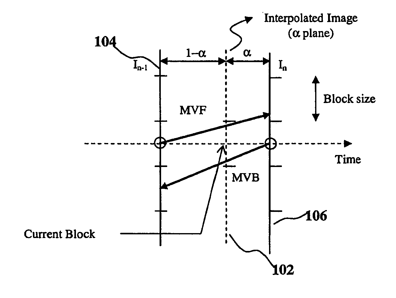
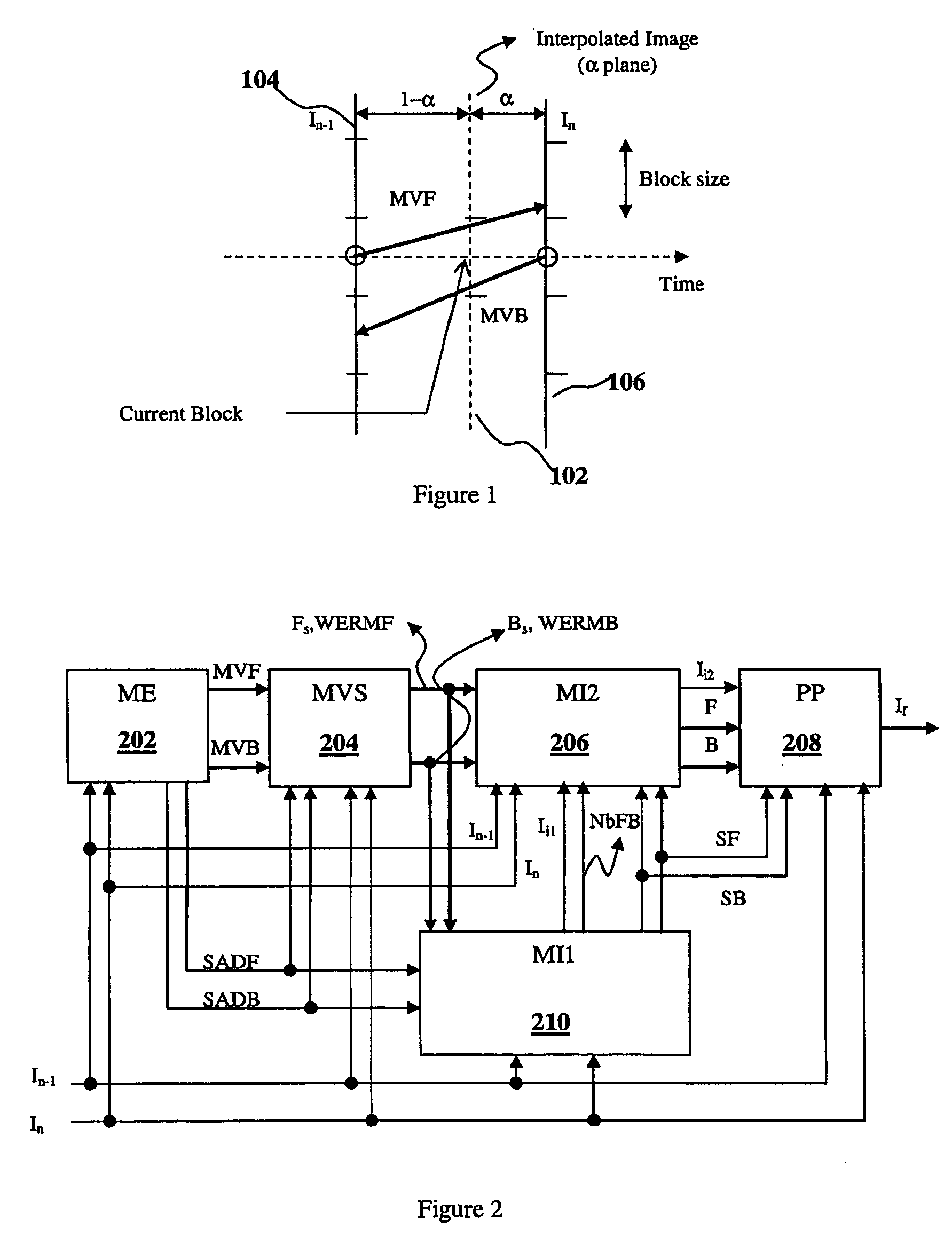
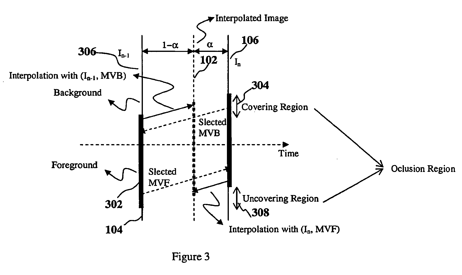
[0048]In a frame rate conversion (FRC) application, the “Halo Effect” is a visual artifact that occurs when a foreground object is moving against a detailed background. A system for reducing the Halo Effect consistently with the present invention includes a pixel-based motion vector (MV) selection, a preliminary interpolation, local shape adaptive windowing for MV foreground / background correction, and a final interpolation with some additional post-processing. The preliminary and final image interpolations are based on occurrence frequency of local Sum of Absolute Differences (SADs) of the forward and backward motion vector estimations. The MV correction for halo reduction can then be based substantially on local image intensities and on local MV variations. Some embodiments are non-iterative techniques that are efficient for image memory usage and communication bandwidth between the image memory and the image processor.

[0049]FIG. 1 illustrates the time position of an interpolated i...


PUM


Abstract

An image interpolator is presented that utilizes a block-based motion estimator to provide block-based motion vectors and a motion vector select coupled to the block-based motion estimator to provide pixel based motion vectors. A first image interpolator provides a first interpolated image from the selected motion vectors. A second image interpolator corrects the selected motion vectors, including a correction for halo reduction. Post processing can be utilized to further reduce the halo effect.

Description

PROVISIONAL PRIOR APPLICATION[0001]U.S. Patent Application Ser. No. 61 / 015,228 Dec. 20, 2007[0002]U.S. Patent Application Ser. No. 61 / 015,970 Dec. 21, 2007US CLASSIFICATIONReferences CitedUS Patents:[0003]U.S. Pat. No. 6,005,639[0004]U.S. Pat. No. 6,011,596[0005]U.S. Pat. No. 6,219,436 B1[0006]U.S. Pat. No. 6,487,313[0007]U.S. Pat. No. 6,625,333 B1[0008]US 2006 / 0072790 A1[0009]US 2007 / 0121725A1[0010]U.S. Pat. No. 7,039,109 B2[0011]U.S. Pat. No. 7,058,227B2OTHER PUBLICATIONS[0012]G. de Haan, “IC for Motion-Compensated De-Interlacing, Noise Reduction and Picture Rate Conversion”, IEEE Trans. on CE, Vol. 45, No. 3, August 1999.[0013]K. Sugiyama, T. Aoki & S. Hangai, “Motion Compensated Frame Rate Conversion Using Normarized Motion Estimation”, 2005 IEEE Workshop on Signal Processing Systems—Design and Implementation (SiPS 2005), Athens, GreeceRELATED APPLICATIONS[0014]This application claims priority to U.S. Provisional Application Ser. No. 61 / 015,228, filed on Dec. 20, 2007, and to U....

Claims


Application Information

Patent Timeline
IPC IPC(8): H04N7/01
CPCH04N19/577H04N7/014
Inventor TRAN, THUY-HA THILEDINH, CHON TAM
Owner QUALCOMM INC
Why Eureka
Try Eureka