Bearing mechanism, motor and storage disk drive apparatus

Inactive Publication Date: 2009-06-25
NIDEC CORP
View PDF11 Cites 18 Cited by
  • Summary
  • Abstract
  • Description
  • Claims
  • Application Information

AI Technical Summary

Benefits of technology

[0011]With the present invention, damage of a thrust plate is prevented by restraining movement of a shaft unit. Furthermore, rigidity is secured without having to overly increase the thickness of a sleeve h

Problems solved by technology

However, in a bearing mechanism with a pivot bearing, a shaft may excessively press the thrust plate because it makes pointwise contact with the thrust plate.
This may cause damage to the thrust plate or plastic deformation in the housing.
Therefore, there is a concern that the

Method used


Image

  • Bearing mechanism, motor and storage disk drive apparatus
  • Bearing mechanism, motor and storage disk drive apparatus
  • Bearing mechanism, motor and storage disk drive apparatus

Examples


Example

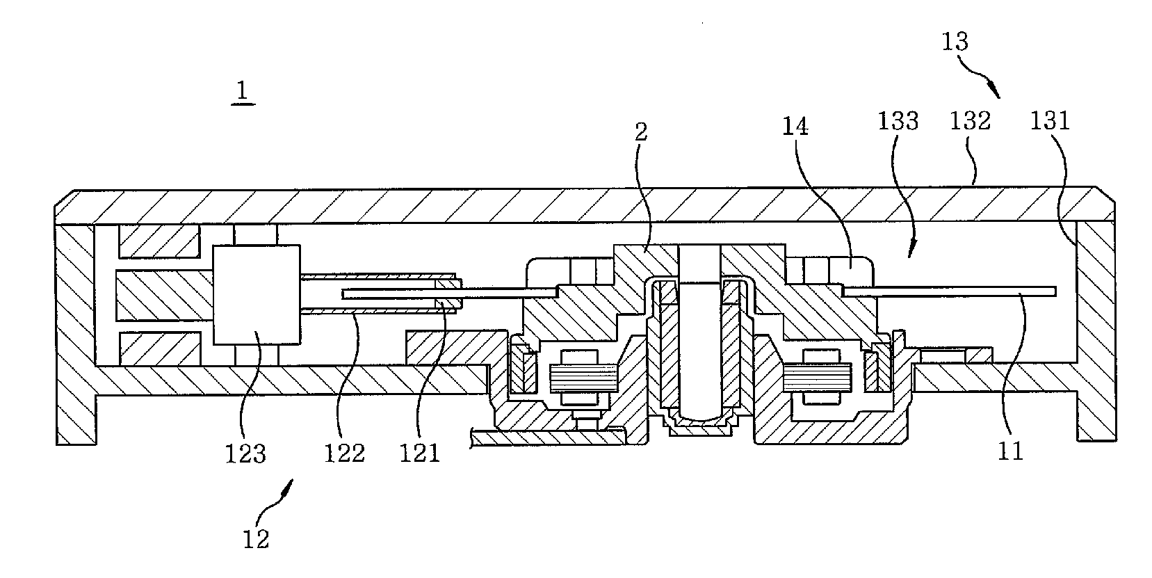
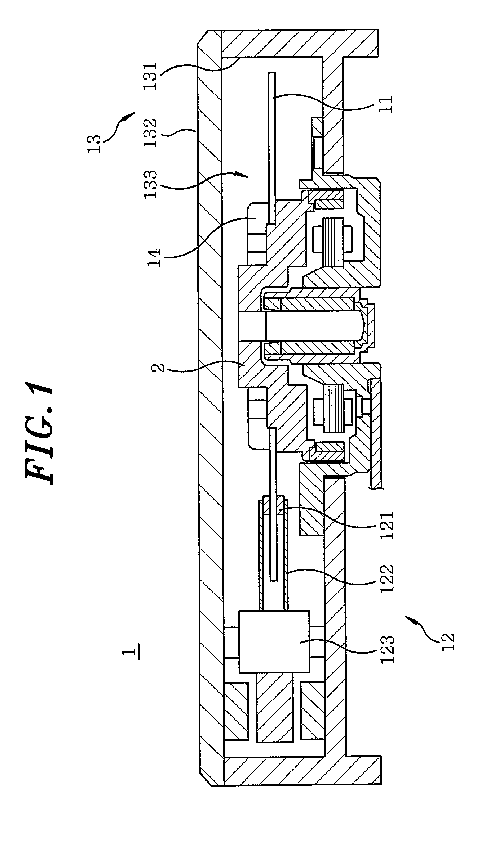
[0025]FIG. 1 is a sectional view showing a storage disk drive apparatus 1 provided with a spindle motor (hereinafter referred to as a “motor”) in accordance with a first embodiment of the present invention, which view is taken along a plane containing a central axis of the apparatus 1. In the description made herein, the terms “upper”, “lower”, “left” and “right” used for explaining the positional relationships and orientations of elements are intended to designate those in the drawings, and not to designate those in a state that they are assembled into an actual device.

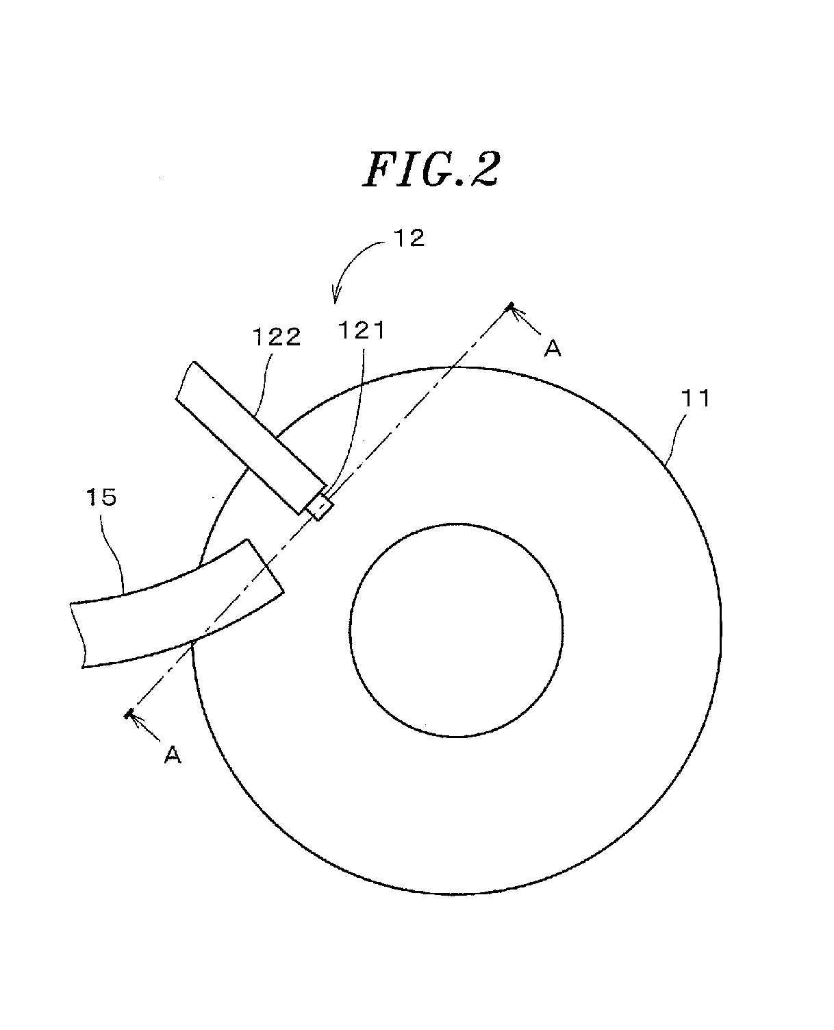
[0026]The storage disk drive apparatus 1 is exemplified as a hard disk drive, and includes a circular plate-like storage disk 11 for storing data; an access unit 12 for reading and writing data from and to the storage disk 11; a motor 2 for rotating the storage disk 11; and a housing 13 for receiving the storage disk 11, the motor 2 and the access unit 12 within an internal space thereof to isolate them from the outs...


PUM


Abstract

A bearing mechanism includes a cylindrical bottom-closed sleeve unit; a shaft unit radially supported by the sleeve unit via a lubricant; and an elastic thrust plate on an inner bottom surface of the sleeve unit to contact an end portion of the shaft unit at a position on a central axis to rotatably support the shaft unit. The shaft unit has a first contact portion, and the sleeve unit has a second contact portion. The contact portions are so arranged that, when a force acting from above the inner bottom surface is applied, movement of the shaft unit is restrained by the contact portions making contact with each other. Further, a distance between the contact portions prior to the force being applied is smaller than the displacement of the shaft unit at which the thrust plate gets so pressed by the shaft unit to be permanently deformed.

Description

FIELD OF THE INVENTION[0001]The present invention relates to a bearing mechanism having a pivot bearing.BACKGROUND OF THE INVENTION[0002]In recent years, there has been proposed a bearing mechanism used for a spindle motor in a storage disk drive apparatus, which includes a dynamic pressure bearing for radially supporting a shaft inserted into a sleeve by a dynamic fluid pressure of a lubricant, and a pivot bearing for axially supporting the shaft by bringing the tip end of the shaft into pointwise contact with a thrust plate.[0003]Japanese Patent Application Publication No. 2005-113987 discloses a pivot bearing in a bearing mechanism, in which a shaft has a lower shaft portion with a spherical tip end, and an upper shaft portion with a diameter smaller than that of the lower shaft portion. The lower shaft portion is inserted into a sleeve in a substantially cylindrical bottom-closed sleeve holder portion. The tip end of the lower shaft portion comes into pointwise contact with a th...

Claims


Application Information

Patent Timeline
IPC IPC(8): G11B17/02F16C32/06H02K5/16
CPCF16C17/10F16C33/107F16C2370/12G11B19/2036H02K5/1675F16C35/02
Inventor SHIRAI, HIROKAZUSEKII, YOICHIGOMYO, MASATO
Owner NIDEC CORP
Why Eureka
Try Eureka