
Method and optical drive for detecting a header region on an optical carrier
Patent Information
- Authority / Receiving Office
- US · United States
- Current Assignee / Owner
- Publication Date
- 2009-06-25
- Estimated Expiration
- Not applicable · inactive patent
Smart Images
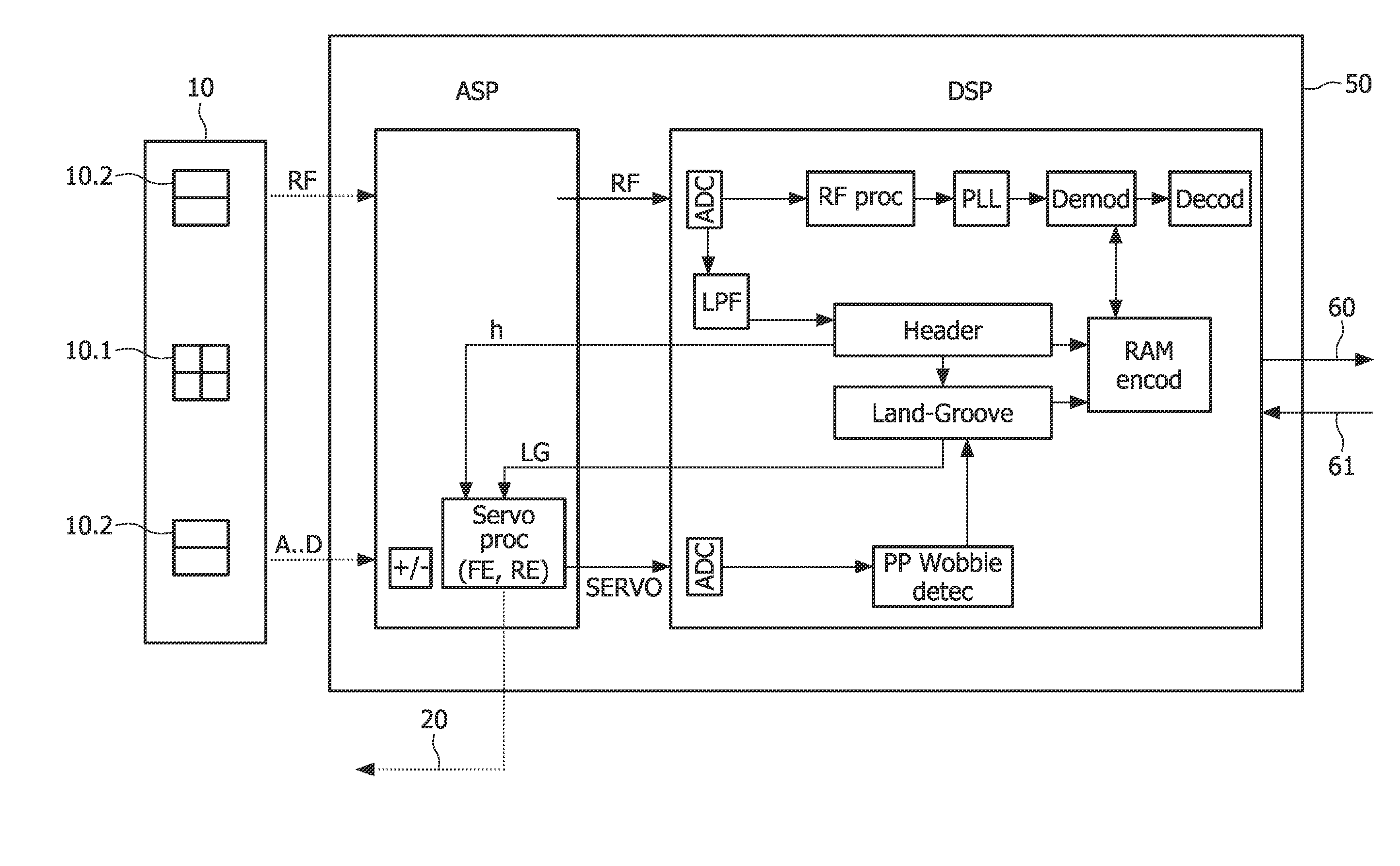
Figure 1 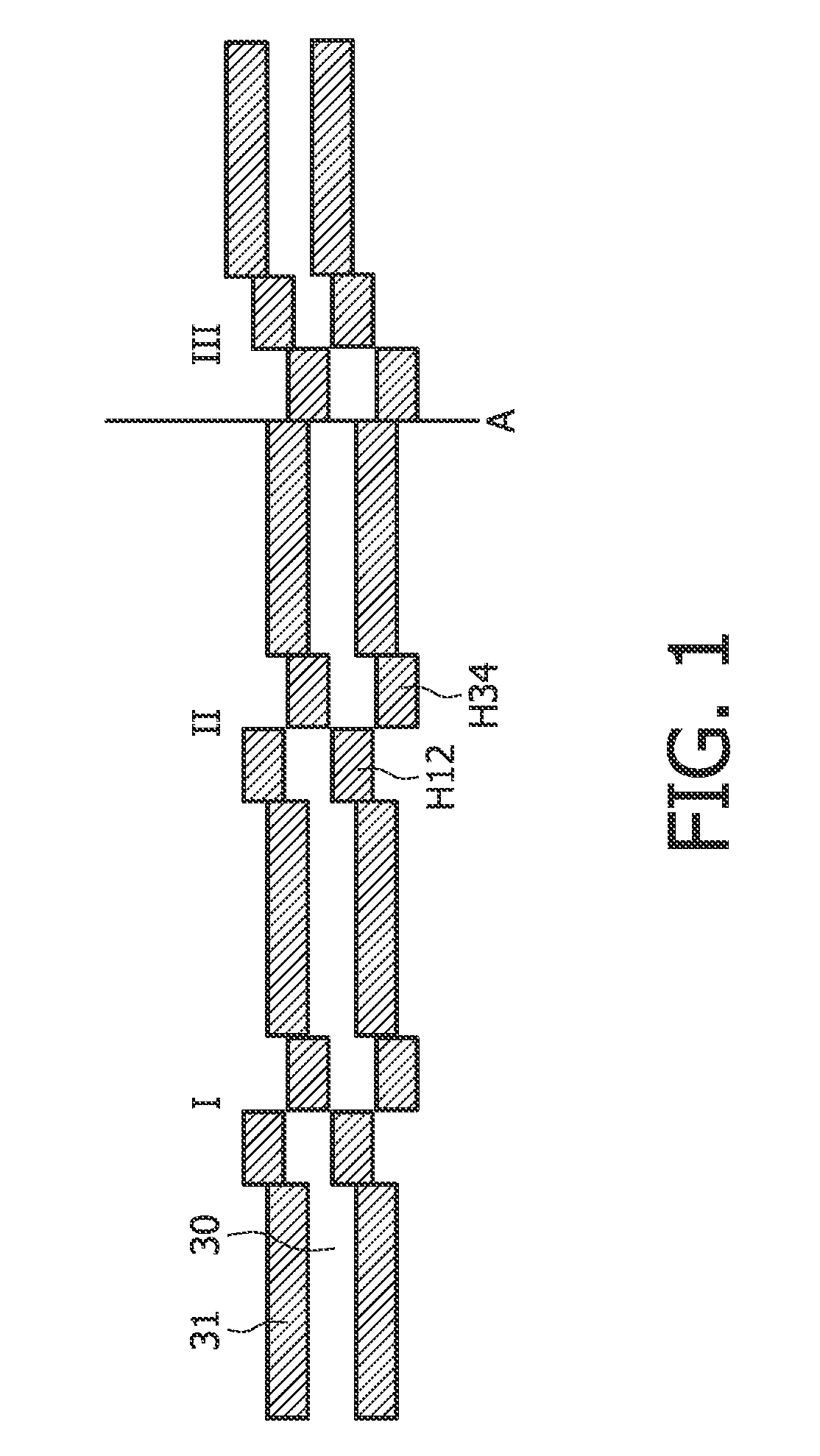
Figure 2 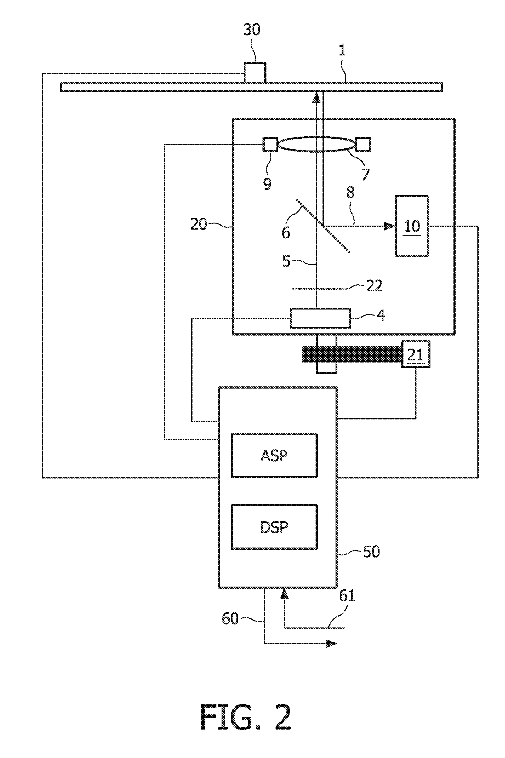
Figure 3
Abstract
Description
FIELD OF THE INVENTION
[0001] The present invention relates to a method of detecting a header region for a writeable optical carrier. Such optical carriers may in particular include a digital versatile disc of the read access memory format (DVD-RAM). The invention also relates to a corresponding optical drive.BACKGROUND OF THE INVENTION
[0002] Optical storage of information on optical carriers or disks such as CDs, DVDs, HD-DVDs and BDs is being increasingly used in more and more applications. The corresponding demand for higher and higher information density (information per area) has given rise to a multitude of different technologies, each technology with various associated advantages and problems.
[0003] Conventionally, the information on the optical carrier is arranged in spiral-like tracks with the information being grouped in blocks, each block having sectors with a header section, a data section, and an error correction code (eec) section. The header section typically contains inf...
Examples
Embodiment Construction
[0039]FIG. 1 is a schematic illustration of the DVD-RAM format. The present invention is particularly suited for application for an optical carrier having a format according to the DVD-RAM standard, but the present application is by no means limited to this specific format and the present invention may also find application for other formats. The header sections I, II and III shown in FIG. 1 are arranged with four headers grouped two by two, the two header groups H12 and H34 being offset half a track pitch in opposite direction relative to each other and to the groove 31 and land 30 center track position. Furthermore, at the intersection A of each revolution of groove 31 and land 30, the last sector groove (land) connects to the first sector of the land (groove) and at the same time the polarity of the two header groups H12 and H34 are changed. Going from header region I to header region II there is no change of polarity, whereas header region III has a change of polarity relative t...