Motor characteristics acquiring apparatus, control apparatus using the acquired motor characteristics, and power window control apparatus

a technology of motor characteristics and acquisition apparatus, which is applied in the direction of motor/generator/converter stopper, dynamo-electric converter control, instruments, etc., can solve the problems of low operation speed, difficulty in accurately determining the rotational speed of the motor, and pulse width of the detection signal

Inactive Publication Date: 2009-06-25
MABUCHI MOTOR
View PDF7 Cites 14 Cited by
  • Summary
  • Abstract
  • Description
  • Claims
  • Application Information

AI Technical Summary

Benefits of technology

[0027]FIGS. 10A and 10B are diagrams to qualitatively show advantageous effects of an exemplary embodiment;
[0028]FIG. 11 is a conceptual diagram showing a method for calculating a rotation period according to a second exemplary emb

Problems solved by technology

When an object is jammed during the rising of the door glass, the operation speed thereof drops due to a reaction force of the load bearing on the object.
A problem with such a rotation detection sensor as described above, however, is that variation, if any, in the polarization of the north and south poles of the magnet can cause errors in the pulse width of the detection signals, which renders accurate determination of the rotational speed of the motor difficult.
Moreover, provision of a plurality of hall elements can cause installation errors of the hall elements also.
That is, each edge interval to be calculated covers one w

Method used


Image

  • Motor characteristics acquiring apparatus, control apparatus using the acquired motor characteristics, and power window control apparatus
  • Motor characteristics acquiring apparatus, control apparatus using the acquired motor characteristics, and power window control apparatus
  • Motor characteristics acquiring apparatus, control apparatus using the acquired motor characteristics, and power window control apparatus

Examples


first exemplary embodiment

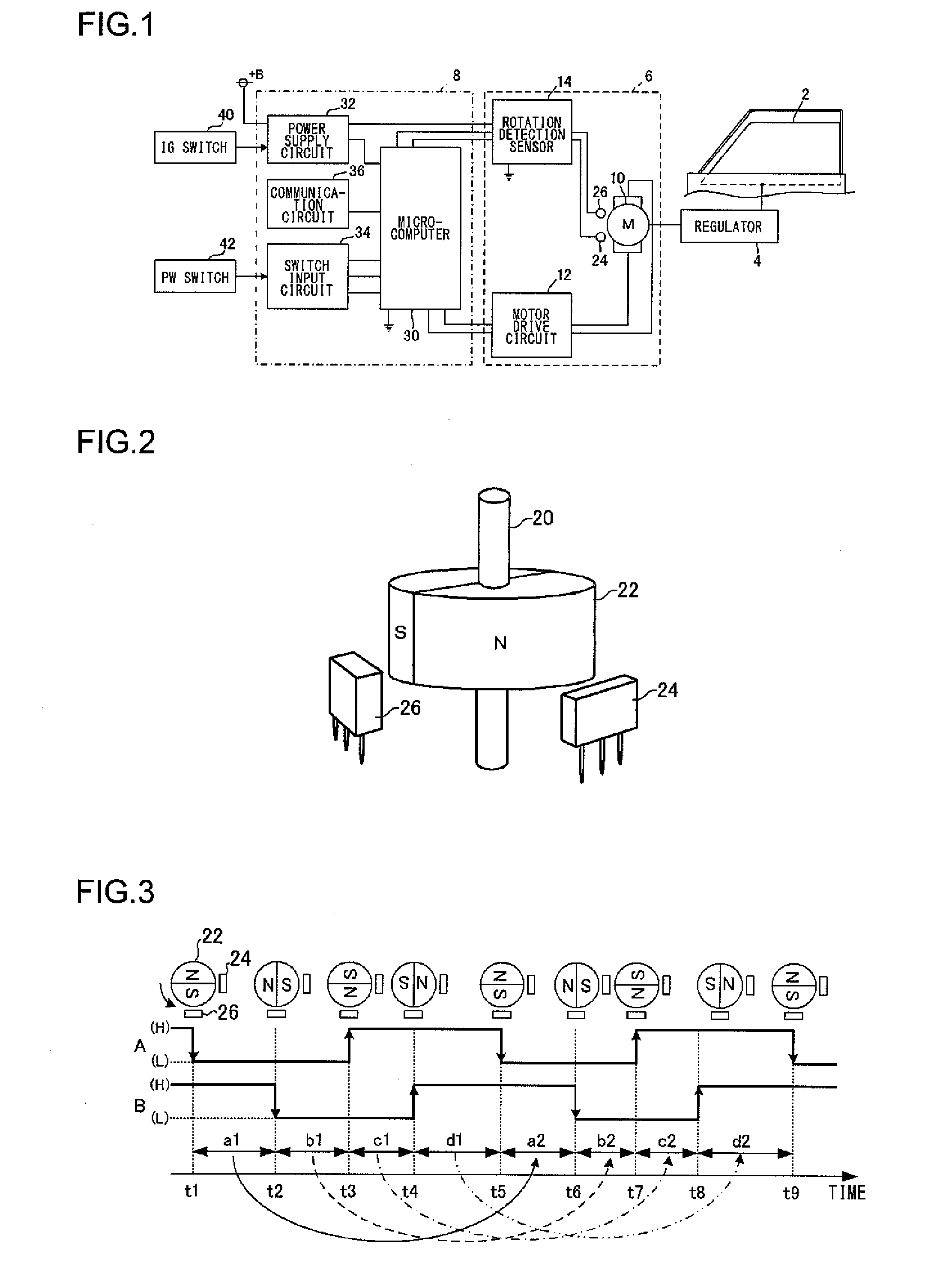
[0041]FIG. 1 shows a schematic constitution of a power window control apparatus according to a first exemplary embodiment of the present invention. FIG. 2 illustrates schematically a structure of a rotation detector for a motor that drives a power window. For convenience of explanation, a power window control apparatus as shown in FIG. 1 is to be understood as one installed in a position operable from the driver's seat.

[0042]As shown in FIG. 1, the power window control apparatus according to the first exemplary embodiment drives and controls a regulator 4 for operating a door glass 2 of a vehicle up and down. The power window control apparatus includes a motor actuator 6 for driving the regulator 4 and a control unit 8 for driving the motor actuator 6.

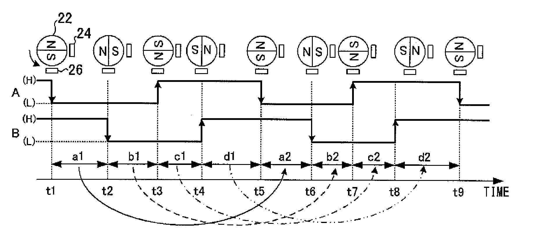
[0043]The motor actuator 6 includes a motor 10 for driving the regulator 4, a motor drive circuit 12 for driving the motor 10, and a rotation detection sensor 14 for detecting the rotation status of the motor 10. The motor 10, whose ro...

second exemplary embodiment

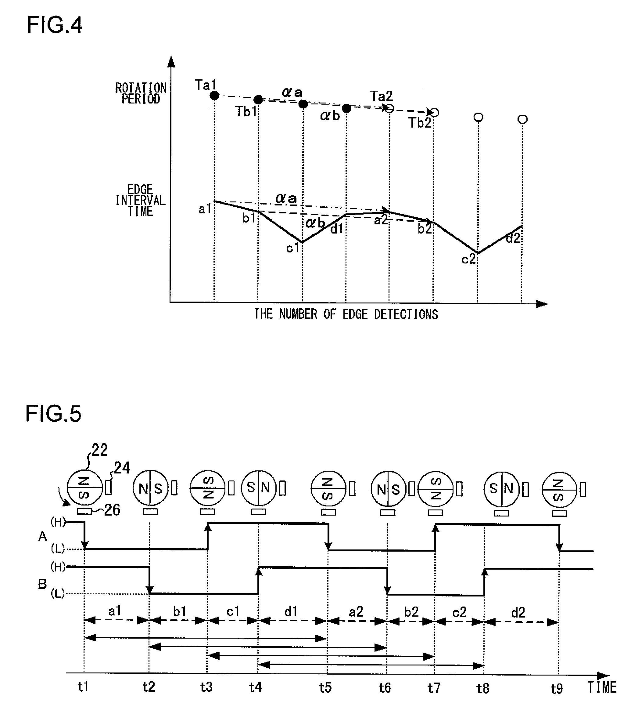
[0081]A description is now given of a second exemplary embodiment of the present invention. This second exemplary embodiment differs from the first exemplary embodiment in that an average edge interval time is used in the calculation processing of calculating the rotation period of the motor 10, and the other features are basically the same as in the first exemplary embodiment. Thus, the structural components of the second exemplary embodiment similar to those of the first exemplary embodiment are given the identical reference numerals when needed and the description thereof is omitted as appropriate.

[0082]FIG. 11 and FIG. 12 are each a conceptual diagram showing a method for calculating the rotation period according to the second exemplary embodiment. FIG. 11 illustrates a method for calculating the reference period. FIG. 12 illustrates a relationship between the edge interval time detected for each edge detection and the rotation period of the motor 10.

[0083]In the above-described...


PUM


Abstract

The rotation period of a motor is subdivided by edge interval times and a rate of change between a currently calculated edge interval time and an edge interval time calculated one rotation of the motor previously is calculated at the detection of each edge. Then the rotation period of the motor is calculated by multiplying a set reference period by the calculated rate of change.

Description

CROSS REFERENCE TO RELATED APPLICATIONS[0001]The present application claims international priority under 35 U.S.C. §119 to co-pending Japanese Patent Application No. 2007-326814 filed 19 Dec. 2007, entitled “MOTOR CHARACTERISTICS ACQUIRING APPARATUS, CONTROL APPARATUS USING THE ACQUIRED MOTOR CHARACTERISTICS, AND POWER WINDOW CONTROL APPARATUS,” the entire content and disclosure of which is hereby incorporated by reference in its entirety.BACKGROUND OF THE INVENTION[0002]1. Field of the Invention[0003]The present invention relates to an apparatus for acquiring the rotational characteristics of a motor as a drive source and a control apparatus for performing control using the acquired motor characteristics.[0004]2. Description of the Related Art[0005]Some motor vehicles have automatic windows called “power windows”, which are so designed that when some foreign object is caught in a closing door glass (window glass), the jamming is detected quickly and the door glass is rolled back in...

Claims


Application Information

Patent Timeline
IPC IPC(8): H02P7/285G01P3/487G01P3/489H02P6/06H02P6/08H02P6/18H02P21/00H02P21/18H02P21/24H02P23/16H02P23/18H02P27/04
CPCE05Y2400/336E05Y2400/554E05F15/41E05Y2900/50E05F15/40E05Y2900/55
Inventor TATEGAMI, TORUFUJII, SHUMPEI
Owner MABUCHI MOTOR
Why Eureka
Try Eureka