Eureka AIR delivers breakthrough ideas for toughest innovation challenges, trusted by R&D personnel around the world.

Method for drying laundry and machine implementing such a method

a technology for drying machines and laundry, applied in the field of drying machines and methods, can solve the problems of poor performance, high differential or hysteresis, and the system described with reference to fig. 1 is not very efficient, and achieves the effect of more reliabl

Inactive Publication Date: 2005-06-21
MERLONI ELETTRODOMESTICI SPA
View PDF9 Cites 15 Cited by
  • Summary
  • Abstract
  • Description
  • Claims
  • Application Information

AI Technical Summary

Benefits of technology

"The present invention provides a method and machine for drying laundry that are more efficient, reliable, and cheaper than existing solutions. The method allows for a quick and simple temperature reach using only one resistance, and maintains a constant temperature to avoid the saw-teeth advancement of thermostats. The machine also complies with standards on electromagnetic compatibility to minimize risks of fault and malfunction. The method and machine use simple and low-cost components."

Problems solved by technology

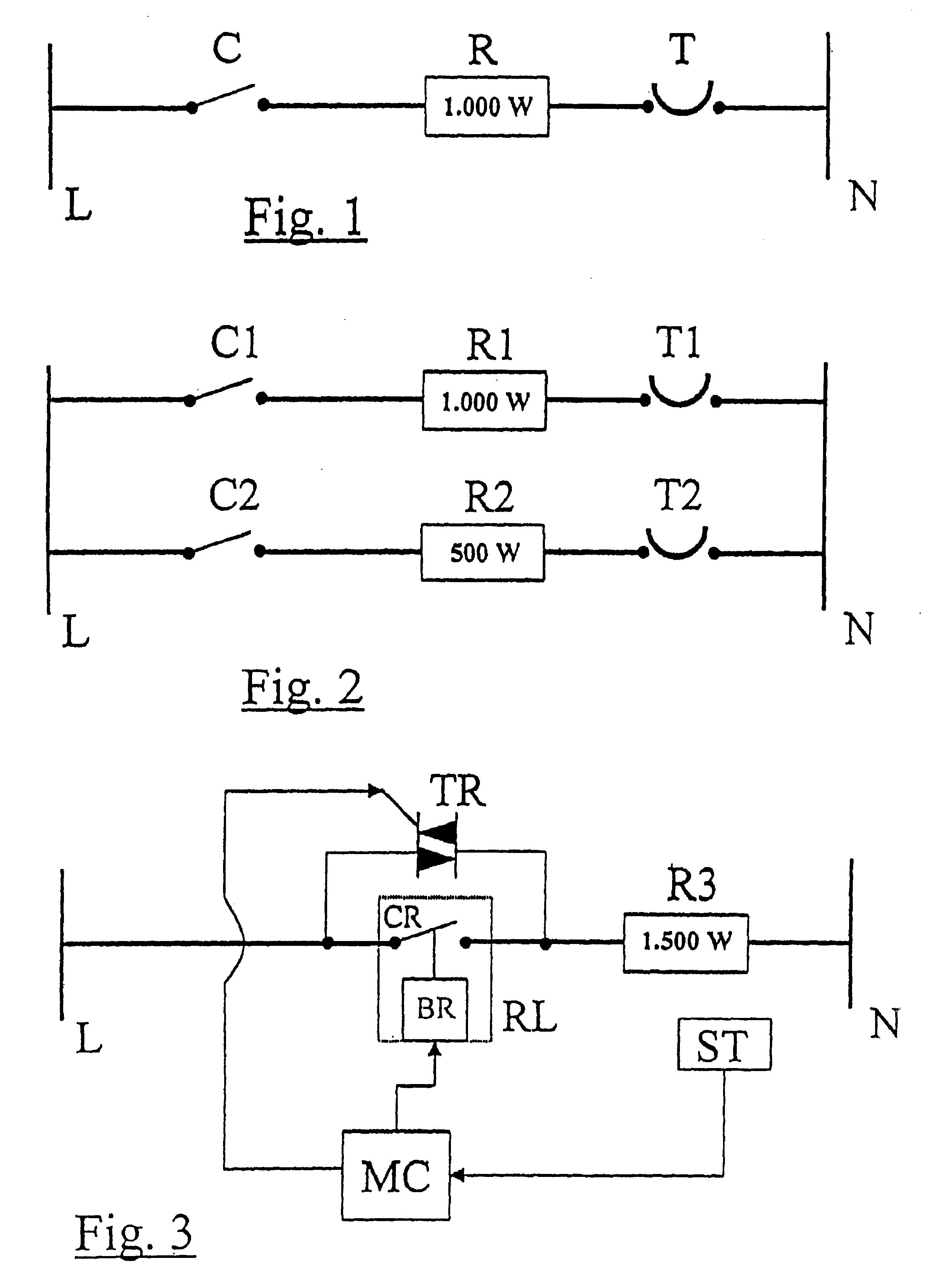
The system illustrated in FIG. 1 represents a simple and cost-effective system, but is featured by a poor performance.
A first drawback related to the solution shown in FIG. 1 is represented by the fact that the control of the supply of the heating element R is assigned to an electromechanical thermostat, which typically has a high differential or hysteresis.
Even if the decrease of the temperature in the tub is relatively fast, it is clear how the system described with reference to FIG. 1 is not very efficient, due to its waste of time and thermal energy, above all considering that during a drying program, particularly in the instance of a high laundry load, the electric contact of the thermostat T will forcedly be subject to a plurality of opening / closing cycles.
Another drawback related to the solution of FIG. 1 is represented by the fact that the heating element R is specifically sized for maintaining the rated drying temperature, i.e. the cited 130° C.
However, due to this sizing, the initial phase of the drying, during which the rise to the rated temperature is realized, requires a relatively long time, i.e. representing a further poor element of the system.
However, this is an expensive solution, in as much as it presumes the use of two heating elements, two control contacts and two thermostats.
However, also this solution is not a very practical one, since it requires the use of two heating elements, two supply contacts and one thermostat.
Apart from the type of control employed for the heating element R2, the above solution would not prevent the problem previously mentioned of the cyclicity of intervention of the thermostat T1, should the safety temperature be exceeded.

Method used


Image

  • Method for drying laundry and machine implementing such a method
  • Method for drying laundry and machine implementing such a method

Examples


Embodiment Construction

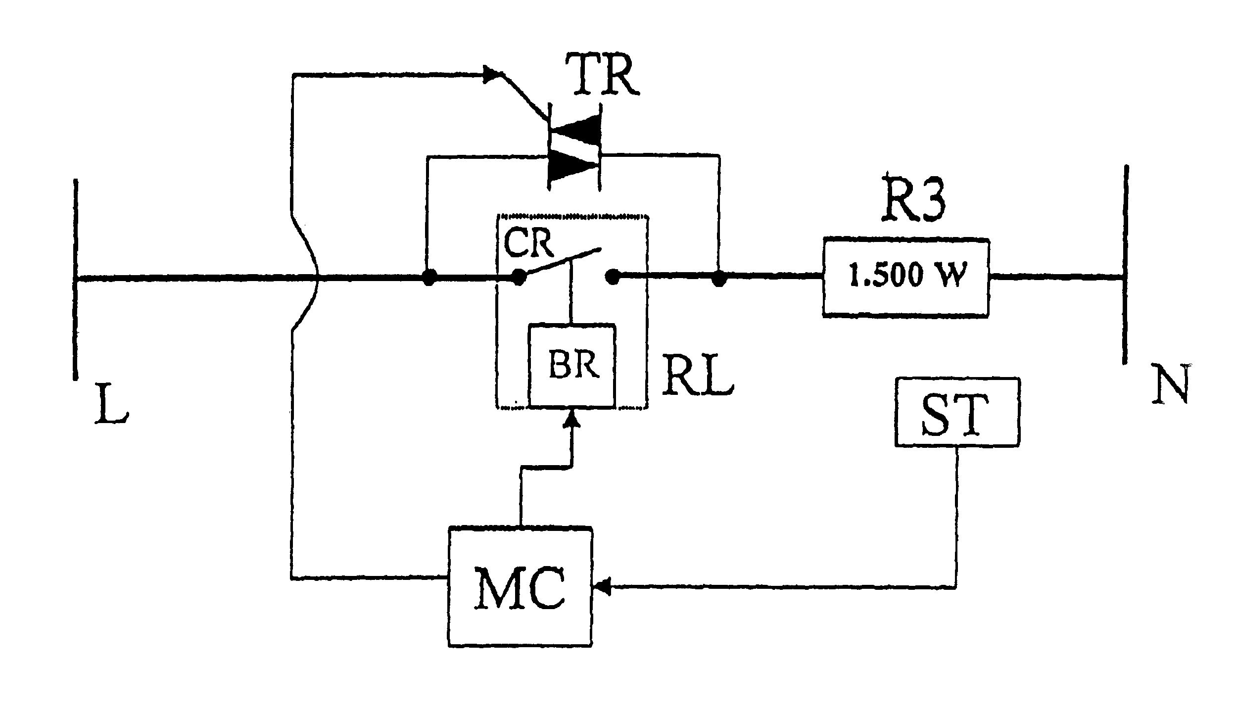
[0043]The basic idea of the present invention is to employ only one air heating resistance, which has a decidedly oversized heating power with respect to the power required for maintaining the normal “steady-state” temperature of drying, so as to reach said temperature very fast and then modulate its heating power in an appropriate way.

[0044]To this purpose, during the initial phase of the drying process, i.e. initial stage of the air heating, the resistance or heating element is supplied with continuously, so as to exploit its maximum heating power and quickly reach a predetermined temperature for the drying air.

[0045]Following the attainment of said predetermined temperature, the power of the heating element is modulated, by alternating supply periods to periods of interruption of its supply, i.e. non-supply periods, in order to manage said power in the steady-state phase for obtaining a substantial constancy of the temperature.

[0046]FIG. 3 represents schematically a possible embo...


PUM


Abstract

Method for drying laundry and a machine able to implement such a method, which provides for the use of only one electric resistance for heating the air utilized for drying purposes.According to the invention, during the starting phase of the drying process, i.e. the initial stage of the air heating, said resistance is applied continuously for exploiting its maximum power and quickly reach a predetermined temperature of the drying air.Following the attainment of said predetermined temperature, a special control circuit causes said resistance to be applied in a shuttered or modulated way, i.e. by alternating application phases to non-application phases within repetitive reference periods, in order to manage the power of the resistance in its steady-state condition for obtaining a substantial constancy of the air temperature.

Description

BACKGROUND OF THE INVENTION[0001]The present invention relates to a method for drying laundry and a machine able to dry laundry implementing such a method.[0002]As known, some types of household appliances have the capability of drying the laundry after washing; typically, these appliances are the so-called wash-and-drying machines performing both the washing and the subsequent drying of the laundry, and laundry drying machines, which are only provided for drying the laundry.[0003]These machines have a drum for containing the laundry to be dried, which is made to rotate for a preset time at a determined speed, while warm air is introduced into the tub wherein the drum is rotating; the drum rotation speed during drying is relatively low, typically about 55 revolutions per minute (r.p.m.); the drying time is generally set manually by means of a dedicated timing device, according to the user's specific needs (i.e., substantially as a function of the degree of drying to be reached and t...

Claims


Application Information

Patent Timeline
Patent Type & Authority Patents(United States)
IPC IPC(8): D06F58/28
CPCD06F58/28D06F2058/289D06F2058/2829D06F2105/28D06F58/38D06F2103/08D06F34/10D06F2103/32
Inventor MARIOTTI, CONSTANTINO
Owner MERLONI ELETTRODOMESTICI SPA
Why Eureka
Eureka Blog
Learn More