
Cannula For An Injection Device, The Cannula Having A Tapered End, And A Method For Manufacturing the Same

a cannula and injection device technology, applied in the field of cannulas for injection devices, can solve the problems of increased pain and unsatisfactory pain, and achieve the effect of reducing the stress on the tool parts

Inactive Publication Date: 2009-06-25
NOVO NORDISK AS
View PDF7 Cites 25 Cited by
  • Summary
  • Abstract
  • Description
  • Claims
  • Application Information

AI Technical Summary

Benefits of technology

[0017]One advantage of this method is that by using a tool which does not comprise two reciprocating tool parts, the risk of manufacturing cannula's with asymmetrical shape is reduced or even eliminated. Moreover, guiding means for ensuring alignment of reciprocating tool parts may be dispensed with whereby a simpler manufacturing process is provided. Furthermore, as the position of the tool is identical for each manufacture of a cannula, the variation of the outer dimensions of the cannula's is reduced considerably.
[0026]The method comprises the step of reducing the hardness of a distal zone of the tubular element, the distal zone extending from the distal end towards the proximal end. The step of reducing the hardness precedes the step of forcing, whereby the force needed to reshape the tubular element is reduced. Furthermore, tear and wear of the tools is reduced.
[0027]In one embodiment the hardness of the entire tubular element is reduced while in other embodiments only that part of the tubular element which will be reshaped is softened. This provides the advantage that the remaining parts of the cannula—i.e. those parts which are not to be reshaped—remains hard, and, thus, do not bend when the tubular element is reshaped.
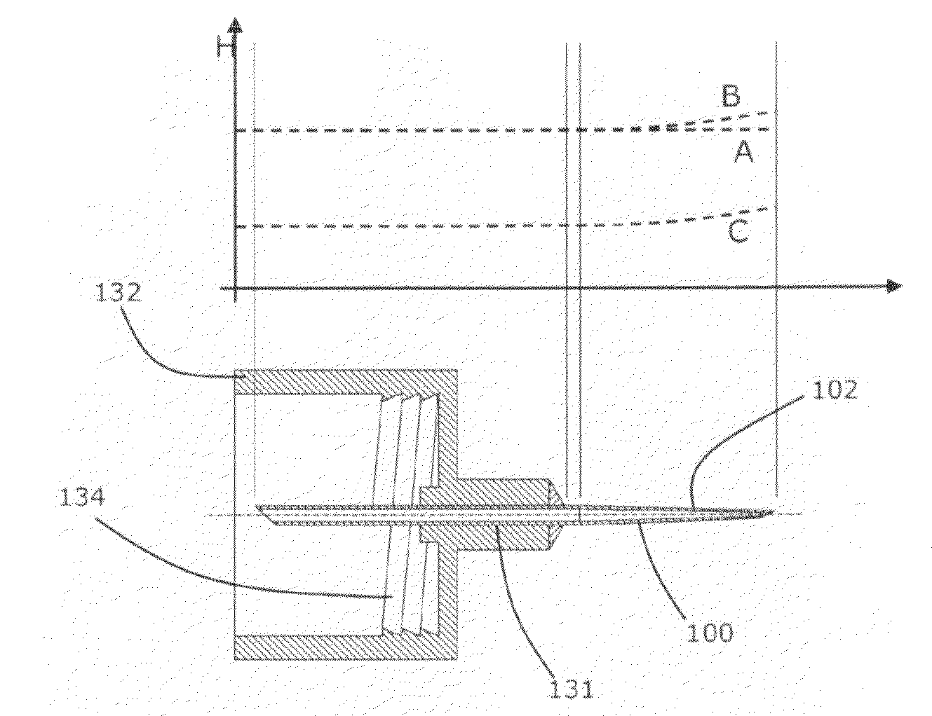
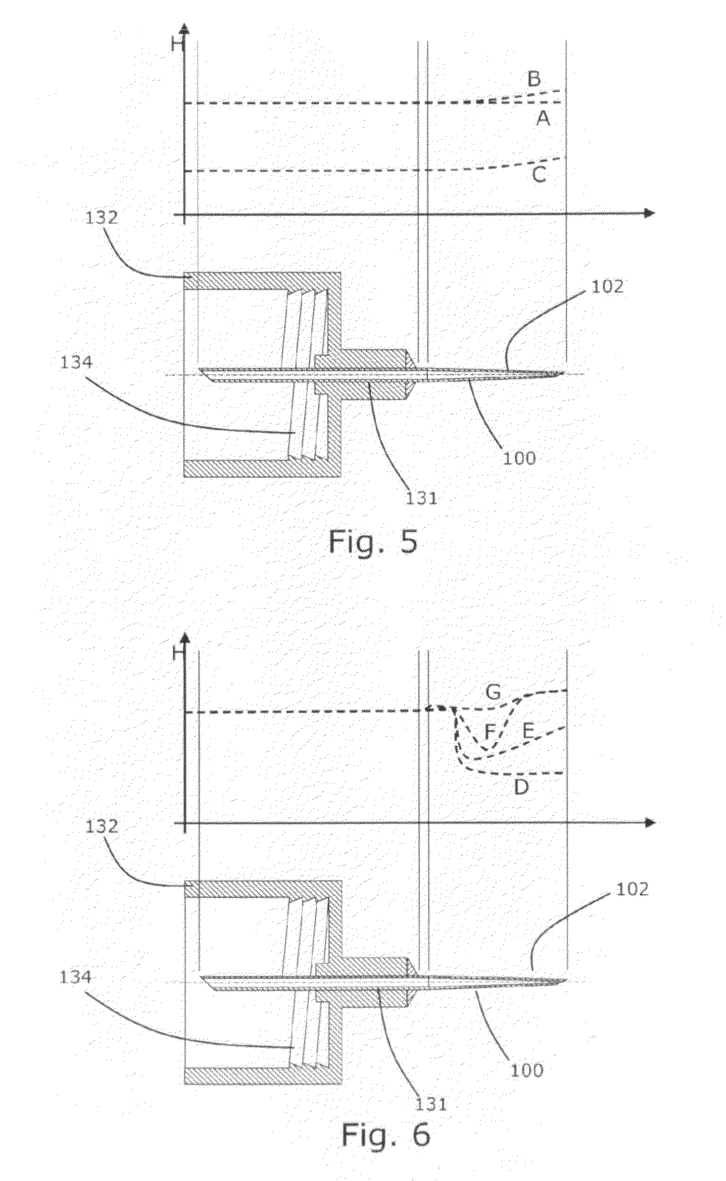
[0040]Normally when manufacturing a tapered cannula, the tapered part is harder than the non-tapered part. As harder parts are more prone to breakage than less hard parts, the result is a cannula having a tendency of breaking in a zone which during use is inserted into the tissue of the user. Breakage inside the user is highly undesirable as it is difficult if not impossible to remove the broken part from the body without surgery. The present invention utilises that softer parts are less prone to breakage, as such softer parts may be bent a plurality of times prior to breakage, relative to harder parts. In one embodiment, the first zone is defined in the tapered part (the tissue penetrating part). Accordingly, the tissue penetrating part is less prone to breakage, whereby breakage inside the patient less likely.
[0042]By providing a tip (the second zone) which is harder than the first zone, the tip point itself is less prone to bending. Thus, any radial force applied to the tip results. in bending in the first zone, whereby a hard tip may be combined with prevention of breakage inside the patient.

Problems solved by technology

Conventional cannula's have relative large diameters, and, thus, cause an undesired high level of pain.
Asymmetrical outer surfaces result in an increased level of pain, as the needle in one direction transverse to its longitudinal direction, is larger than necessary.

Method used


Image

  • Cannula For An Injection Device, The Cannula Having A Tapered End, And A Method For Manufacturing the Same
  • Cannula For An Injection Device, The Cannula Having A Tapered End, And A Method For Manufacturing the Same
  • Cannula For An Injection Device, The Cannula Having A Tapered End, And A Method For Manufacturing the Same

Examples


Embodiment Construction

[0057]The invention will now be described in further detail with reference to the drawings in which:

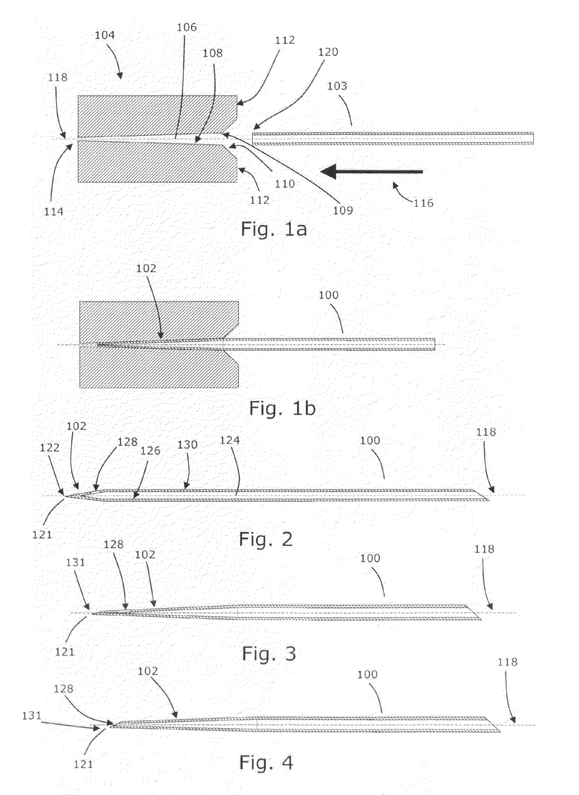
[0058]FIGS. 1a-b disclose steps in the method according the first aspect of the invention,

[0059]FIGS. 2-4 disclose tapered cannula's according to the third aspect of the invention, and

[0060]FIGS. 5-6 disclose the hardness of cannula's annording to the third aspect of the invention.

[0061]FIGS. 1a and 1b disclose steps in the method for manufacturing a cannula 100 with a tapered end portion 102. Initially an tubular element 103 and a tool 104 defining a tapered cavity 106 are provided. The cavity 106 defines a shape-forming zone 108 and a guiding zone 110 which extends between an outer surface 112 and the shape-forming zone 108. In a transition 109 between the shape-forming zone 108 and the guiding zone 110 the diameter of the two zones are substantially identical. The diameter of the shape-forming zone 108 decreases from the transition 109 towards a bottom part 114 of the cavity i.e. i...


PUM

PropertyMeasurementUnit
Diameteraaaaaaaaaa
Diameteraaaaaaaaaa
Diameteraaaaaaaaaa

Abstract

A cannula (100) for an injection device, the cannula defining a tapered end part termination (102) in a distal end for insertion into the tissue of a living being, wherein the hardness of the cannula decreases in the direction of the distal end. A tool (104) for providing a tapered portion of a cannula, the tool defining a tapered cavity (106). A method of manufacturing a cannula defining a tapered end part, by forcing a distal end of an tubular element into a tapered cavity of a tool.

Description

FIELD OF THE INVENTION[0001]The present invention relates to a cannula for an injection device, the cannula defining a tapered end part termination in a distal end for insertion into the tissue of a living being. Especially, the present invention relates to a cannula wherein the hardness of the cannula decreases in the direction of the distal end. Moreover, the present invention relates to a tool for providing a tapered portion of a cannula, the tool defining a tapered cavity. Furthermore, the present invention relates to a method of manufacturing a cannula defining a tapered end part, by forcing a distal end of an tubular element into a tapered cavity of a tool.BACKGROUND OF THE INVENTION[0002]The pain experienced by a patient when introducing a cannula into the patient's tissue is highly dependent on the diameter and the shape of the cannula. Conventional cannula's have relative large diameters, and, thus, cause an undesired high level of pain. In order to overcome this problem, n...

Claims


Application Information

Patent Timeline
IPC IPC(8): A61M5/32A61M5/00B21D22/20
CPCA61M5/3286B21G1/00B21C5/00A61M5/329
Inventor CHRISTOFFERSEN, LASSE WENGELKLINT, HENRIK SONDERSKOVNIELSEN, KARL BRIANANDERSEN, MICHAEL
Owner NOVO NORDISK AS
Learn More