

Table saw
- Summary
- Abstract
- Description
- Claims
- Application Information
AI Technical Summary
Benefits of technology
Problems solved by technology
Method used
Image

Examples
first embodiment
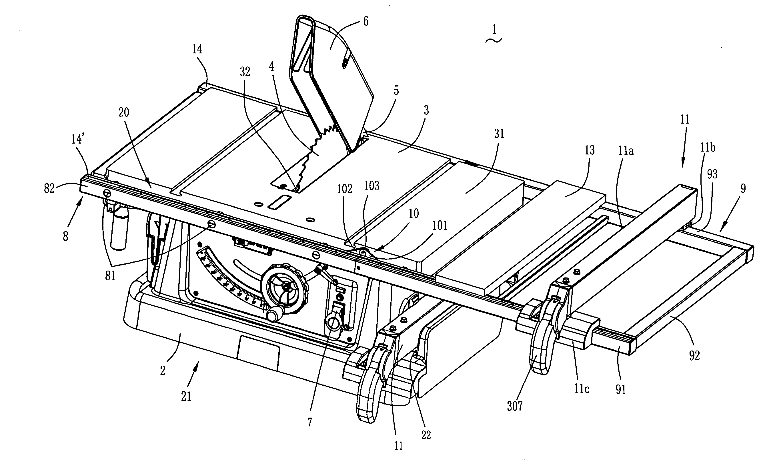
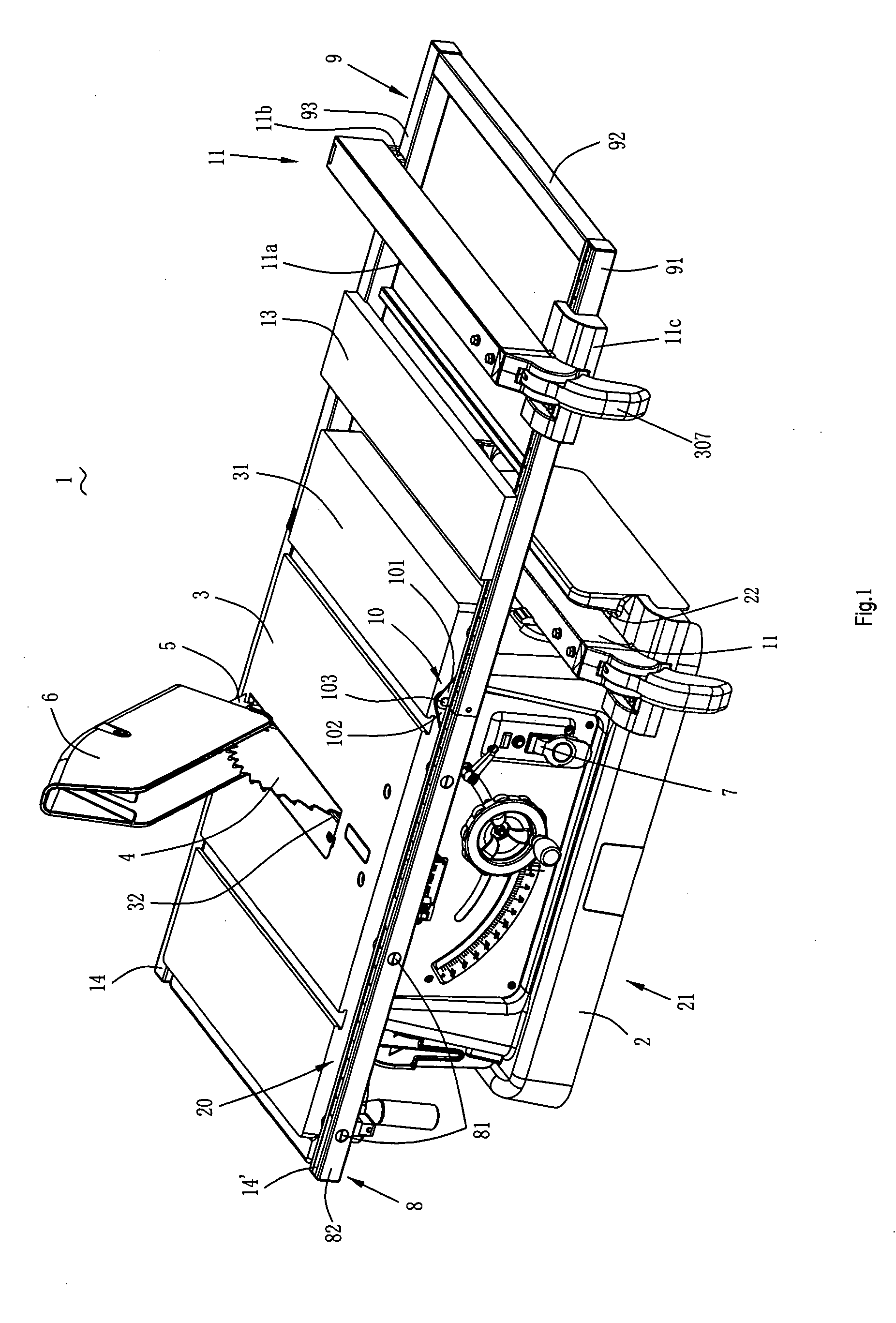
[0059]Referring to FIG. 1, a table saw 1 according to the invention comprises a base 2 having a receiving cavity 21. A circular cutting blade 4 is mounted within the receiving cavity 21 and is driven by a motor (not shown). A storage cavity 22 is formed at an upper periphery of the base 2 and a substantially rectangular stationary worktable 3 is disposed on and supported by the base 2. The worktable 3 has a planar upper work surface 31 for supporting a workpiece. The upper work surface 31 includes a transverse cutting slot 32 through which the cutting blade 4 partially extends for cutting. The cutting blade 4 is used to cut a material such as wood that is pushed laterally along the upper work surface 31.
[0060]A riving knife 5 is disposed behind the cutting blade 4 and operated as a splitter to prevent two cut workpiece parts from closing on one another. A blade guard 6 at least partially encloses the blade 4 and pivotally associates with the riving knife 5 to keep the cutting blade ...
fourth embodiment
[0073]FIG. 18 shows the present invention which is similar to the aforementioned embodiments. The worktable 3c has a planar upper work surface 31c for supporting a workpiece which includes a cutting slot 32 through which the cutting blade 4 partially extends for cutting the workpiece. The table saw 1c comprises an auxiliary support 300 which is a substantially U-shaped framework which includes a pair of parallel guide rods 301, 302 respectively located at opposite edges of the worktable 3c and a connecting rod 303 connected between the first guide rod 301 and the second guide rod 302. Each of the first guide rod 301, second guide rod 302 and the connecting rod 303 has an upper surface which together define a first support surface and has a bottom surface which together define a second support surface. The first support surface and the second support surface are respectively parallel to the work surface 31c when the auxiliary support 300 is in the extended position or in the folded p...
PUM
| Property | Measurement | Unit |
|---|---|---|
| Length | aaaaa | aaaaa |
Abstract
Description
Claims
Application Information