Spring Arrangement For Spring Drive Unit And Spring Drive Unit Comprising Spring Arrangement

a technology of spring drive and spring arrangement, which is applied in the direction of snap-action arrangement, wound spring, contact mechanism, etc., can solve the problems of inherently unstable compressed state, higher risk of buckling, and disadvantage of adding extra elements to the structure, and achieve cost-effective effects

Inactive Publication Date: 2009-07-02
ABB (SCHWEIZ) AG
View PDF6 Cites 1 Cited by
  • Summary
  • Abstract
  • Description
  • Claims
  • Application Information

AI Technical Summary

Benefits of technology

[0012]The object of the present invention is to provide a spring arrangement for spring drive units in general, and in particular for spring drive units arranged in operating devices for driving and controlling the opening and closing of an electrical switching apparatus, such as a switch or a circuit breaker, which arrangement is light and cost effective.
[0015]The foreseen parameters of the spring in the present circumstances are the length of the spring, the diameter (width) of the spring and diameter of the used wire for the spring. It is in particular the ratio between length and width that is used when choosing the spring. By means of the present invention is obtained a spring arrangement that provides a stable spring and where no guiding tubes are needed, it has fewer components than in prior art, less weight, it is cheaper and more cost effective.
[0016]According to an aspect of the present invention, the pullrod is provided with a joint on a part of the pullrod that is located between the first pullrod end, where the pullrod is connected to the first spring end, and the frame plate. By means of providing a joint on the pullrod, is achieved the advantage of limiting the sideways movement of the unguided first end of the spring. During compression, the unguided spring end does not move linearly, instead it bends or rotates to the side so that the spring ends do not stay parallel to each other. When the spring is released, which is a very fast event, the unguided spring end may start swinging or rotating and this may cause damage to anything that is close to the spring end. In spring drive units where there are two springs, one closing spring and one opening spring, if one of the springs starts swinging it may damage the other spring. This will be prevented by having a joint on at least one of the pullrods. It is desirable that the position of the unguided spring end is predictable for a given load.
[0019]According to a further aspect of the invention, the location of the joint is decided such that the weight of the spring is minimized.

Problems solved by technology

When the springs are charged or loaded, they are in a compressed state that is not inherently stable.
They tend to buckle or roll if they are compressed into the unstable range, and consequently, they require some kind of guiding to prevent buckling.
This also has the disadvantage of adding extra elements to the structure.
Consequently, the risk for buckling is higher for the closing spring and the demands on the guiding tube are higher.

Method used


Image

  • Spring Arrangement For Spring Drive Unit And Spring Drive Unit Comprising Spring Arrangement
  • Spring Arrangement For Spring Drive Unit And Spring Drive Unit Comprising Spring Arrangement

Examples


Embodiment Construction

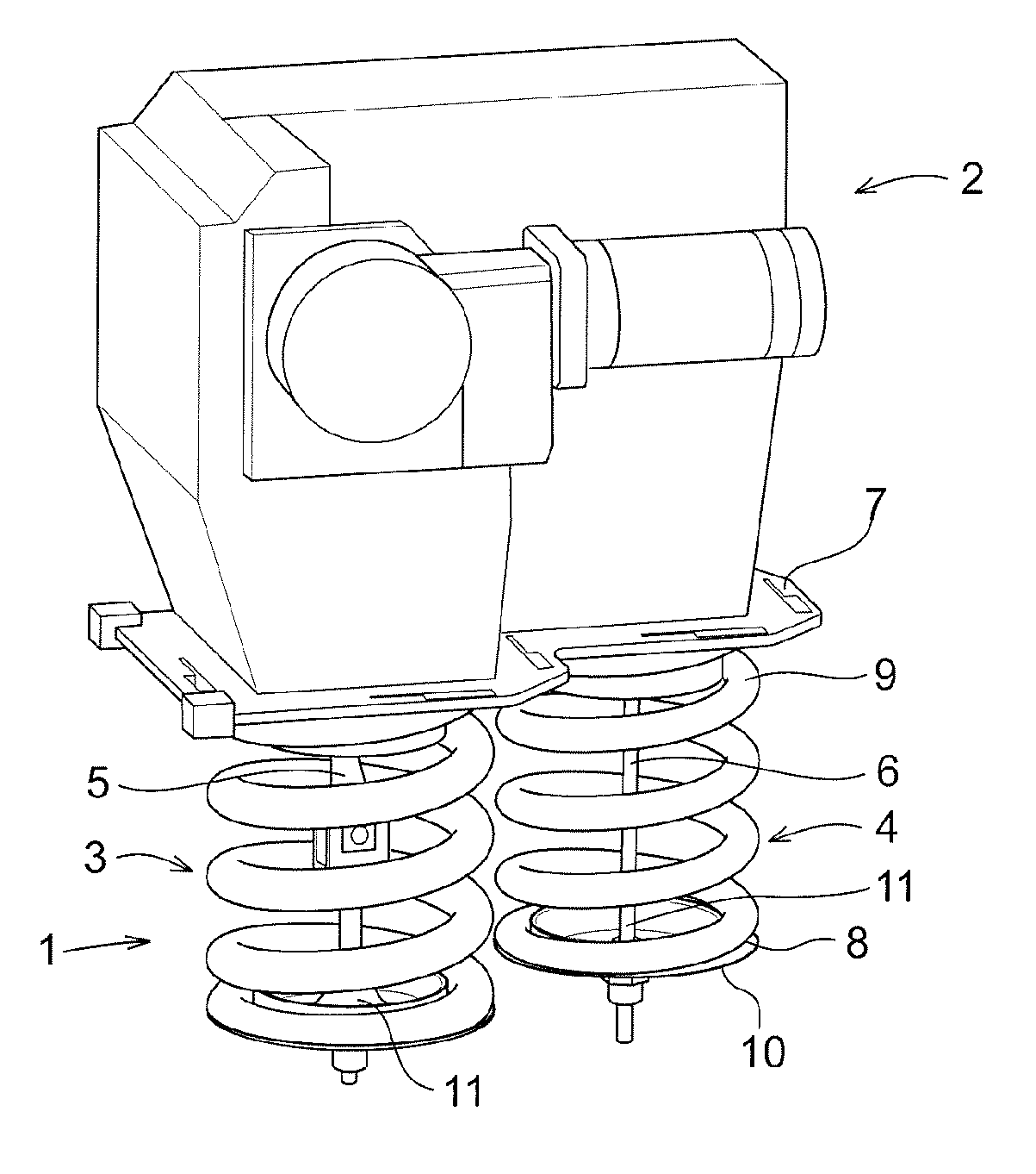
[0027]In FIG. 1 is shown an embodiment of a spring arrangement 1 according to the present invention, installed on a spring drive unit 2 used in electrical switch gear, such as a circuit breaker for medium and high voltages. The main parts and the operation of a spring drive unit used for circuit breakers and switches have already been described above.

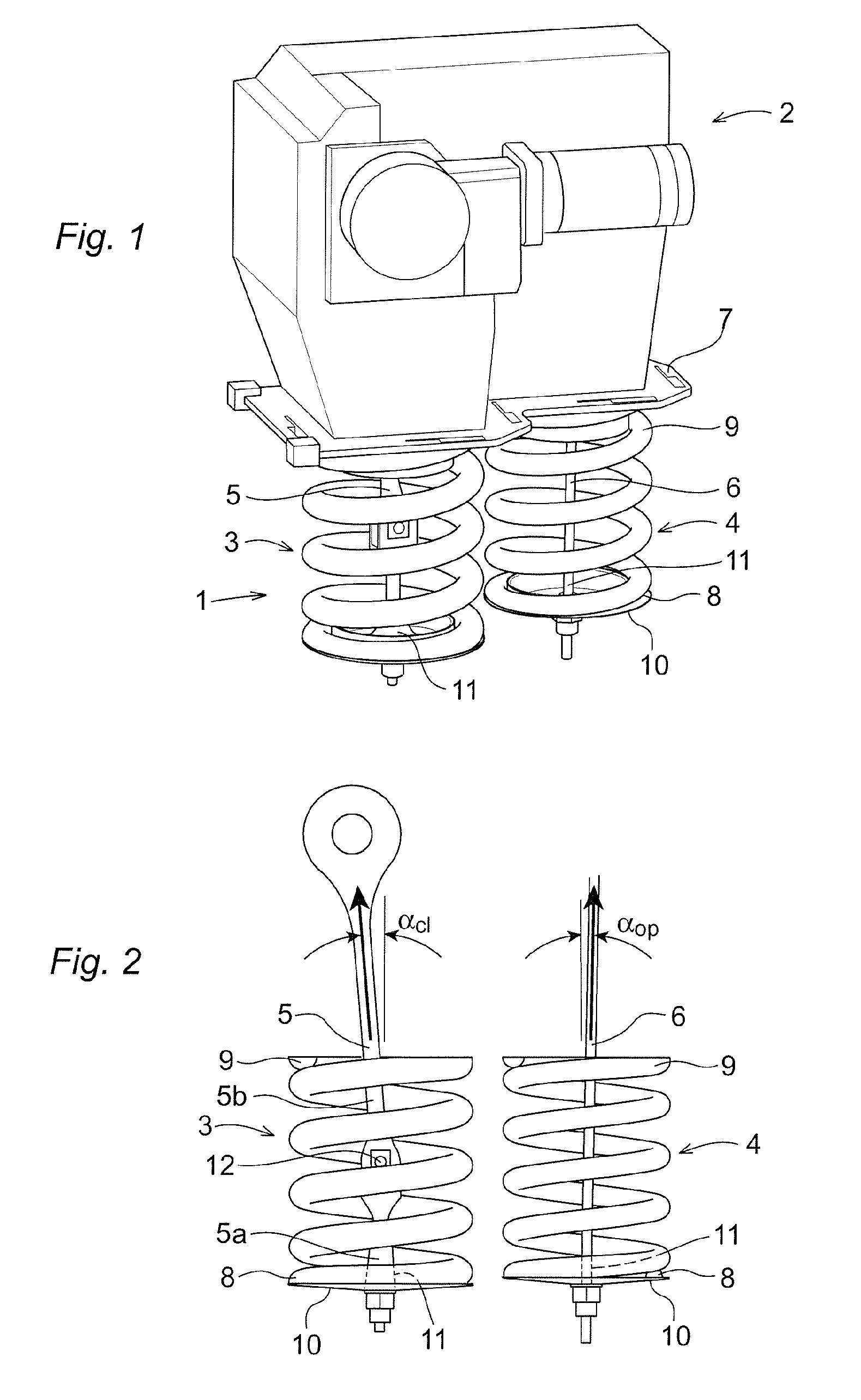
[0028]The basic components of a spring drive unit are two springs, one closing spring 3 for closing the switch and one opening spring 4 for opening the switch. Since many of the details of the opening spring 4 and the closing spring 3 are identical, some of the reference numbers for these details are only indicated for one of the springs, namely the opening spring. Each spring is connected to a charging and discharging mechanism (not shown) inside the housing of the spring drive unit 2, by means of pullrods 5, 6. Each spring has a lower first spring end 8 to which a first pullrod end 11 is connected, e.g. via a spring disc 10, and an up...


PUM


Abstract

The invention describes a spring arrangement for spring drive unit, which spring arrangement comprises a spring, a pullrod connected at a first pullrod end to a first spring end of the spring and connected at an opposite second pullrod end to a rotary shaft of the spring drive unit, a frame plate against which a second spring end of the spring is mounted and the frame plate being provided with an opening through which the pullrod extends to be connected to the shaft. Further, the first spring end of the spring, to which the pullrod is connected, is unguided, and the parameters of the spring are chosen in response to the operating conditions of the spring drive unit such that the spring is stable during operation.

Description

CROSS-REFERENCE TO RELATED APPLICATIONS[0001]The present application claims priority of European patent application No. 07124149.1 filed on Dec. 28, 2007, the content of which is incorporated herein by reference.FIELD OF THE INVENTION[0002]The present invention relates to a spring arrangement for a spring drive unit, e.g. for driving and controlling the opening and closing of an electrical switching apparatus, such as a switch or a circuit breaker. The said switching apparatus is meant to be used in a high or a medium voltage transmission or distribution network and is thus used at voltages ranging from one kilovolt to several hundreds of kilovolts. The spring drive unit may operate circuit breakers of all types, e.g. gas, oil or vacuum insulated circuit breakers of the live tank or dead tank type.[0003]Spring drive units can also be used in other applications. In principle, they may be used anywhere where there is a need to move something very fast.[0004]The present invention also ...

Claims


Application Information

Patent Timeline
Patent Type & Authority Applications(United States)
IPC IPC(8): H01H5/00
CPCH01H33/40H01H3/3026
Inventor TREDOUX, JOHANNESJACOBSSON, STAFFAN
Owner ABB (SCHWEIZ) AG
Why Eureka
Try Eureka