

Lighting controller of lighting device for vehicle
a technology for lighting devices and vehicles, applied in the direction of electric variable regulation, process and machine control, instruments, etc., can solve the problems of increasing weight or raising the cost of a lighting device for a vehicle, and achieve the effects of preventing heat resistance and durability in each semiconductor light source from being deteriorated, and reducing weight, size and cos
- Summary
- Abstract
- Description
- Claims
- Application Information
AI Technical Summary
Benefits of technology
Problems solved by technology
Method used
Image

Examples
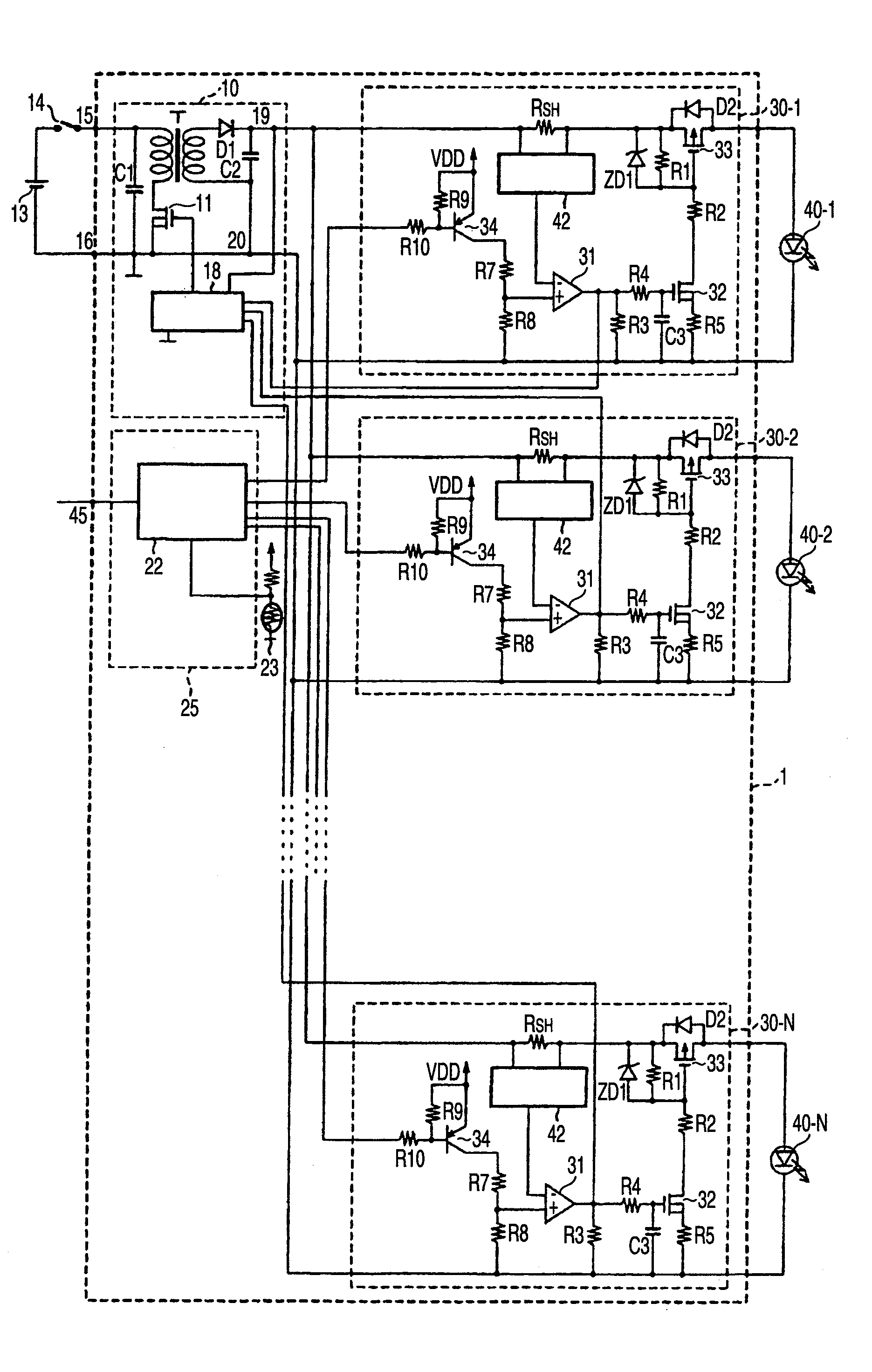
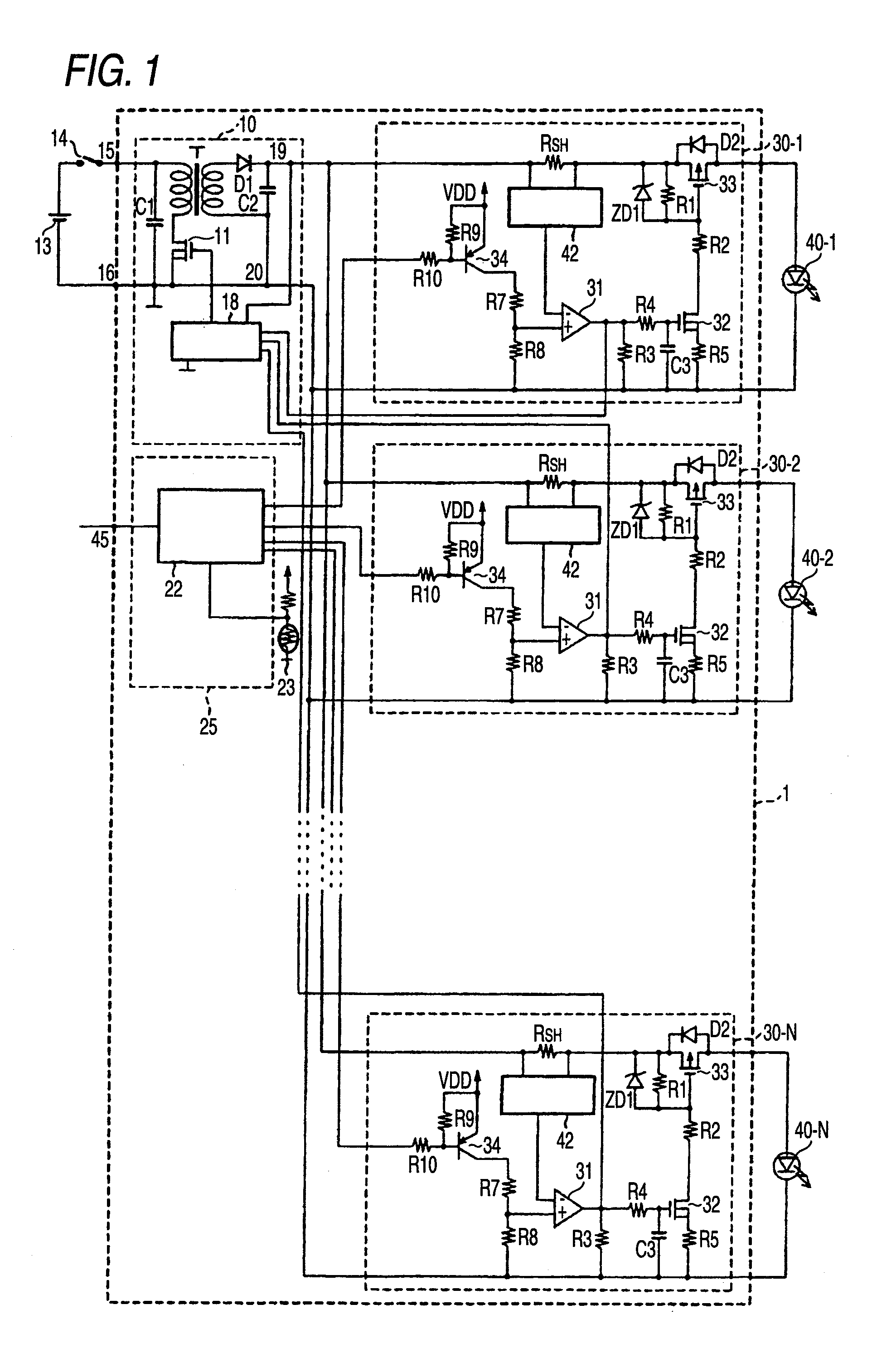
first embodiment
[0046]Although the temperature detector 23 is disposed in a light emitting device in the first embodiment, it may be disposed in a radiating member (not shown) provided in the lighting controller 1 or a housing of a light source unit constituting a lighting device for a vehicle.
[0047]An operation of the lighting controller 1 according to the first embodiment will be described below. FIG. 3 is a graph showing a relationship between a temperature (° C.) detected by the temperature detector and a mean current (A) supplied to the LED. FIG. 4 is a graph showing a relationship between the temperature (° C.) detected by the temperature detector and a duty (%) of a current supplied to the LED.
[0048]The CPU 22 controls each of the current driving portions 30-1 to 30-N in order to decrease the LED driving current supplied to the LEDs 40-1 to 40-N in order of a priority based on thermal environment information which will be described below upon receipt of a temperature detecting signal sent wh...
second embodiment
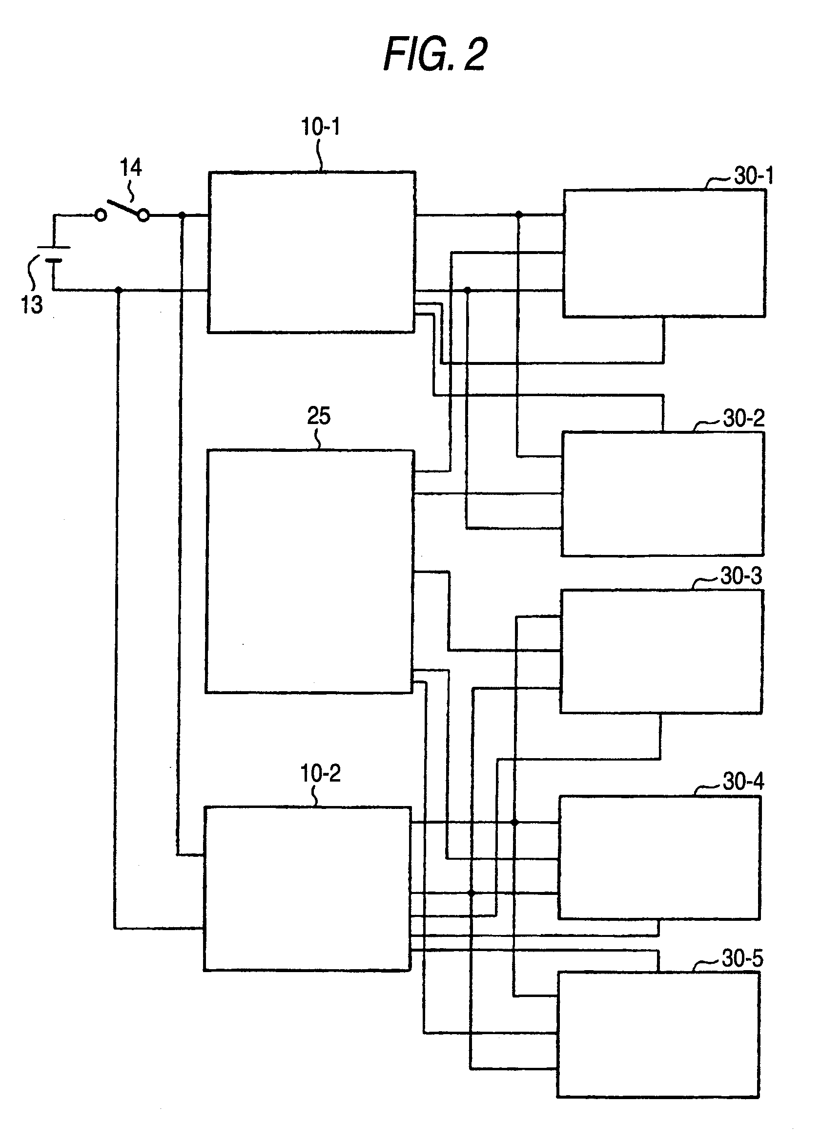
[0071]A lighting controller of a lighting device for a vehicle according to the invention will be described below with reference to FIG. 2. FIG. 2 is a block diagram showing a lighting controller in the case in which a plurality of switching regulators is provided.
[0072]The second embodiment is different from the first embodiment in that the switching regulators are provided. In the following description of the second embodiment, therefore, description of the same portions as those in the first embodiment will be omitted.
[0073]In a situation in which an ambient temperature of the LED is raised so that the thermal environment of the LED is harsh, the thermal environment is harsh for a switching regulator having a function for supplying a driving current.
[0074]For example, in the case in which an LED driving current is supplied through current driving portions 30-1 and 30-2 from a switching regulator 10-1 to the LEDs 1 and 2 having a high use frequency (a harsh thermal environment), t...
PUM
 Abstract
Description
Claims
Application Information