Apparatus and method of selecting components for a reconfigurable impedance match circuit

a technology of impedance match and component selection, applied in the field of broadband wireless radio frequency (rf) communications, can solve the problems of invalidating the static matching case, affecting the performance of the current system, and potentially limiting the bandwidth performance of the system

Active Publication Date: 2009-07-02
THE ARIZONA BOARD OF REGENTS ON BEHALF OF THE UNIV OF ARIZONA
View PDF8 Cites 53 Cited by
  • Summary
  • Abstract
  • Description
  • Claims
  • Application Information

AI Technical Summary

Benefits of technology

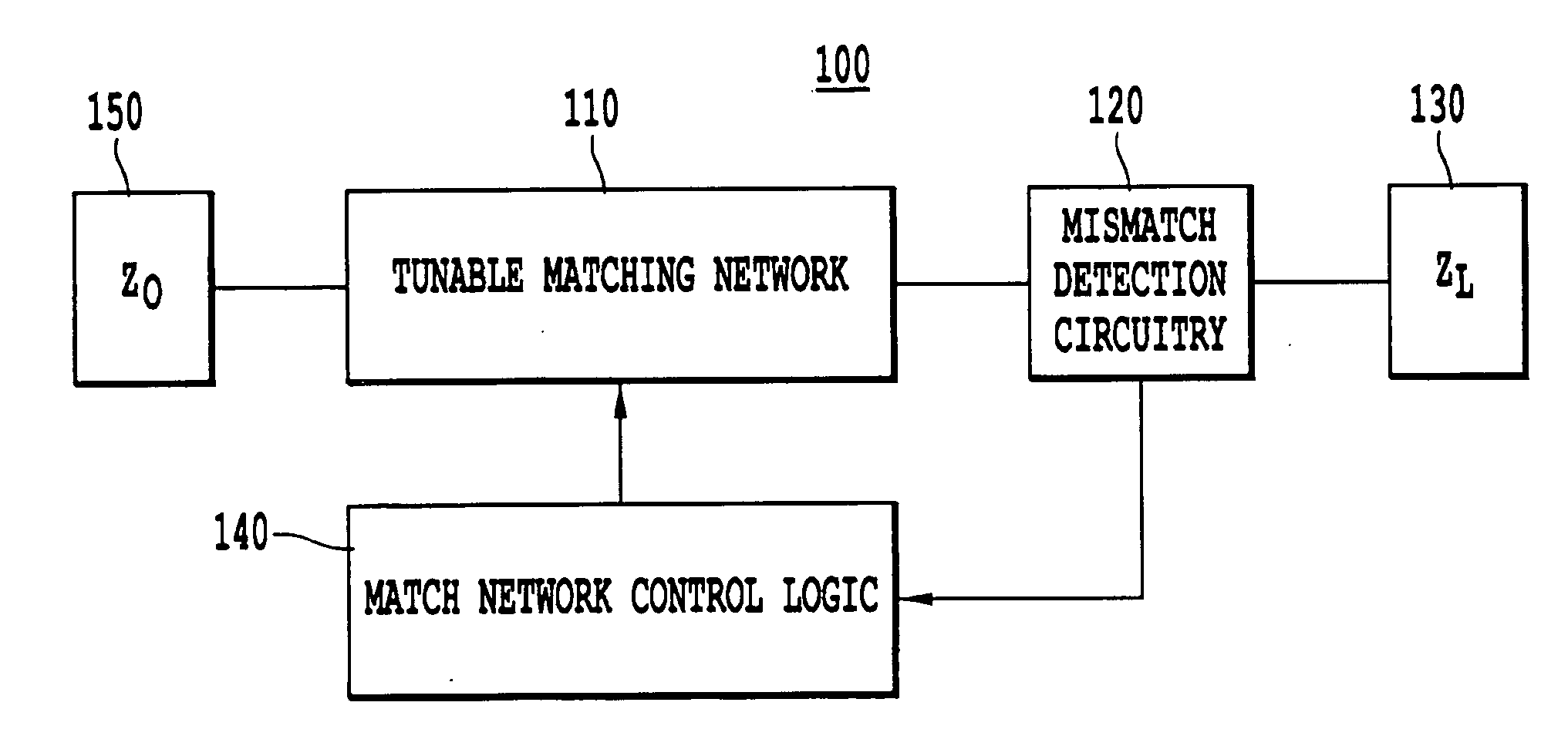
[0015]A broadband reconfigurable matching circuit can be used to correct impedance mismatch. In the past, reconfigurable networks functioned over very narrow bandwidth and required user interaction to decide the b

Problems solved by technology

With this increased need the inadequacies of current systems has become apparent.
An often overlooked but potentially highly limiting factor in the bandwidth performance of a system is the impedance match between important elements in the system.
However, this approach may not adequately account for significant circuit element impedance changes that may occur during the life of the system, which may invalidate the static matching case.
Since the cellular phone needs to radiate a certain amount of energy and less is now being radiated due the impedance mismatch, the phone reacts by increasing the output from the transmitting circuit, resulting in a an efficiency decrease, which may not be prevented when using a static matching network.
A problem with this approach lies in the aspect that a discrete set of loads can be matched.
Since it was essentially the same circuit as proposed in Papapolymerou, the impedance matching structure proposed by Lu may also suffer from low bandwidth and discrete tuning limitations.
H

Method used


Image

  • Apparatus and method of selecting components for a reconfigurable impedance match circuit
  • Apparatus and method of selecting components for a reconfigurable impedance match circuit
  • Apparatus and method of selecting components for a reconfigurable impedance match circuit

Examples


synthesis example

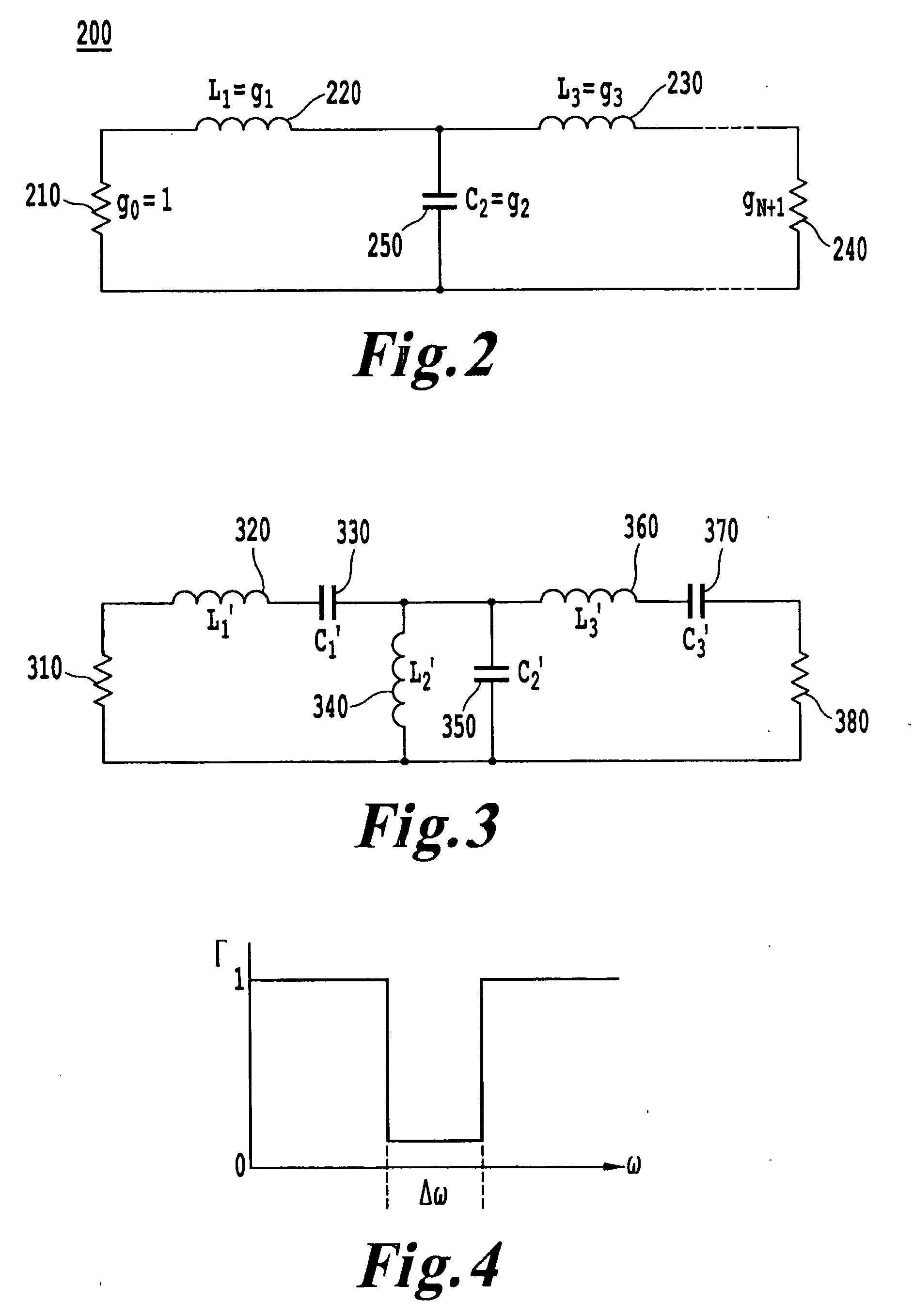
Network Synthesis Example

[0142]Various alternative approaches may be used when selecting the elements for reconfiguring the network. For example, capacitor banks connected with MEMS switches may be used for reconfiguration of the network, as described above. Further, varactor diodes used in conjunction with a novel impedance matching topology will be described below. The present inventors have determined that a suitable varactor diode should preferably operate over the entire frequency range desired for tuning, have high Q, have a large variable capacitance range, and have a package size making it easily implemented in a high frequency circuit.

[0143]An example of a suitable varacter diode is the MPV1965 manufactured by Microsemi. The MPV1965 has a useable capacitance range that spans 0.2 pF to 5 pF. However, the impedance of the stub or interconnecting line connected to the varactor diode may be most easily varied near the middle of the varactor diode's capacitance range.

[0144]In th...


PUM


Abstract

A method of selecting component values for an analog circuit includes identifying a cost function that evaluates similarity between an approximate frequency response function and a preferred frequency response function for at least one characteristic of the functions, determining the approximate frequency response function of the analog circuit based on an approximate component value, and changing the approximate component value based on a determined magnitude of similarity between the preferred frequency response function and the approximate frequency response function for the at least one characteristic. An impedance matching apparatus includes a mismatch detection circuit that produces a difference between source and load impedances, a match network controller that produces a control value based on the difference, and a reconfigurable varactor match network including at least one stub mounted varactor having a capacitance controlled by the control value to match the source and load impedances.

Description

CROSS-REFERENCE TO A RELATED APPLICATION[0001]This application claims priority to co-pending U.S. provisional application No. 60 / 736,117, filed on Nov. 10, 2005, which is incorporated herein by reference in its entirety.BACKGROUND OF THE INVENTION[0002]1. Field of the Invention[0003]The present invention relates to the field of broadband wireless radio frequency (RF) communications, and in particular to a reconfigurable impedance match circuit, which may be used in broadband wireless devices and a method for selecting component values for analog circuits.[0004]2. Discussion of the Background[0005]In the past decade the need for broadband communications has increased rapidly. With this increased need the inadequacies of current systems has become apparent. In order to increase performance much research has been done on different modulation schemes and codecs, different antennas, and transmission circuits. An often overlooked but potentially highly limiting factor in the bandwidth per...

Claims


Application Information

Patent Timeline
IPC IPC(8): H03H7/38G01R27/28
CPCH01P5/04
Inventor MELDE, KATHLEEN LOWEWHATLEY, RICHARD B.
Owner THE ARIZONA BOARD OF REGENTS ON BEHALF OF THE UNIV OF ARIZONA
Why Eureka
Try Eureka