Method and apparatus for monitoring a material medium

a transmission medium and monitoring method technology, applied in the direction of line transmission details, instruments, electric signalling details, etc., can solve the problems of inability to determine the cause of the problem, inability to operate or physically compromise the material medium, and waste significant labor, time and money, etc., to achieve a low labor-intensive monitoring approach and fast

Inactive Publication Date: 2009-07-02
AT&T LABS
View PDF18 Cites 18 Cited by
  • Summary
  • Abstract
  • Description
  • Claims
  • Application Information

AI Technical Summary

Benefits of technology

[0011]These limitations are avoided, in accordance with one embodiment of the current invention, by monitoring a material medium with at least one diagnostic sensor, and using an electromagnetic wave (EM) signal, such as a radio frequency (RF) signal, to wirelessly transmit the sensor data. The diagnostic sensor may measure the operational health of the mat

Problems solved by technology

Unfortunately, it is common for a portion of the material medium to experience an environmental condition or acute stress that causes the material medium to become inoperable or physically compromised.
Currently, significant labor, time and money are spent in trying to determine the location and cause of a material medium's compromise.
Even when a location of a problem in the material medium is identified, the reason for the problem is often not determined.
The inability to determine a cause of the problem may be due, at least in part, to the extended time needed to determine the cause.
By the time the fault is located, the cause of the problem may have already dissipated or relocated.
Alternatively, if the problem was

Method used


Image

  • Method and apparatus for monitoring a material medium
  • Method and apparatus for monitoring a material medium
  • Method and apparatus for monitoring a material medium

Examples


Embodiment Construction

[0043]There are multiple industries which rely upon long stretches of material medium in order to deliver a service to disperse customers. Examples include (1) the telecommunications industry and (2) the electrical power industry. Effective delivery of these services requires that the integrity of the material medium be maintained.

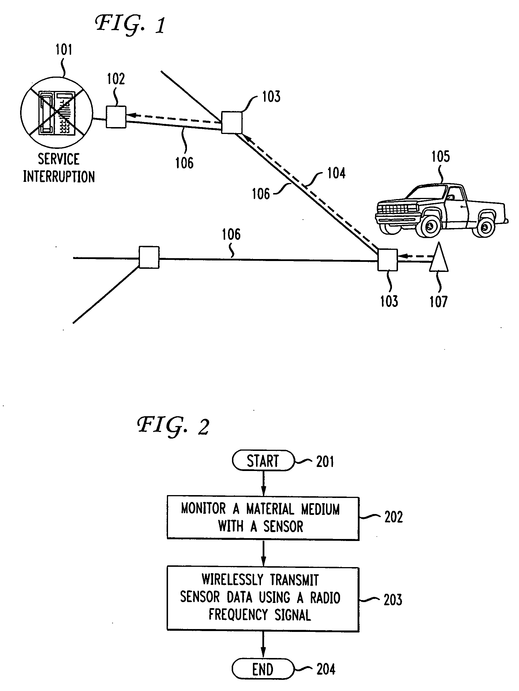
[0044]However, with so many miles of material medium, it is common for a portion of material medium to experience some environmental condition or acute stress that causes the material medium to become inoperable or physically compromised. Currently, significant labor, time and money are spent in trying to determine the location and cause of such a compromise.

[0045]FIG. 1 shows an exemplary prior art system for troubleshooting a failed telecommunication's material medium. A customer, noticing a telephone service interruption, 101, contacts a telecomm service provider and informs the service provider of an inoperable telephone line.

[0046]In order to locate t...


PUM


Abstract

A material medium, such as an optical fiber or electrical cable, is commonly used to carry services, such as telecommunications or energy service. The current invention identifies the following problems which may be encountered when monitoring a material medium. They are: (1) requiring a time and labor intensive investigation to find a fault, (2) needing a significant change in a current material medium infrastructure to support a monitoring effort, or (3) reducing available bandwidth in a material medium due to a monitoring device intruding into the material medium to send data. These problems are solved, in accordance with a feature of the current invention, by monitoring a material medium with at least one diagnostic sensor, and using an electromagnetic (EM) signal, such as radio frequency (RF), signal to wirelessly transmit the sensor data. The diagnostic sensor may measure the operational health of the material medium, or may measure local environmental conditions around the material medium. Using an EM signal, such as RF, to wirelessly transmit sensor data allows for a fast, low labor monitoring approach. Additionally, it avoids a need to either; (1) transfer the data by intruding into the monitored material medium, or (2) set up an independent material medium system to transfer the data.

Description

BACKGROUND OF THE INVENTION[0001]The present invention relates generally to a material transmission medium, and more particularly to method of monitoring the transmission medium.[0002]There are multiple industries which rely upon long stretches of a material medium in order to deliver a service to dispersed customers. Examples of such industries include (1) telecommunications and (2) electrical power. Effective delivery of these services requires that the integrity of the material medium be maintained.[0003]Unfortunately, it is common for a portion of the material medium to experience an environmental condition or acute stress that causes the material medium to become inoperable or physically compromised. Currently, significant labor, time and money are spent in trying to determine the location and cause of a material medium's compromise.[0004]Even when a location of a problem in the material medium is identified, the reason for the problem is often not determined. The inability to ...

Claims


Application Information

Patent Timeline
IPC IPC(8): G08B21/00
CPCG01D21/02G01D21/00G01R31/085G01R31/08H04B10/079
Inventor COTY, CONSTANCEJI, LUSHENGMILLER, ROBERTWORSTELL, HARRY
Owner AT&T LABS
Why Eureka
Try Eureka