Apparatus and method for single-pass, gradient-based motion compensated image rate conversion

a technology of image rate and gradient, applied in the field of image rate upconversion, can solve the problems of annoying artifacts, difficult focus of human eye, uneven motion of objects in consecutive images,

Active Publication Date: 2009-07-02
ATI TECH INC
View PDF97 Cites 20 Cited by
  • Summary
  • Abstract
  • Description
  • Claims
  • Application Information

AI Technical Summary

Problems solved by technology

As is known, sample and hold upconversions such as the 3:2 pulldown create annoying artifacts called motion judder effects in areas where objects move with respect to consecutive images in the source image sequence.
In other words, the motion of objects in consecutive images is not smooth in prior art sample and hold upconversions.
As a result, the human eye has difficulty focusing on it.
These techniques, however, fail because motion judder is still perceived by the human eye.
The block matching method, however: (1) is not accurate at the sub-pixel level without using expensive processing resources; (2) is expensive to avoid error; and (3) requires recursive algorithms.
Additionally, in order to avoid any error in detection of motion, expensive and

Method used


Image

  • Apparatus and method for single-pass, gradient-based motion compensated image rate conversion
  • Apparatus and method for single-pass, gradient-based motion compensated image rate conversion
  • Apparatus and method for single-pass, gradient-based motion compensated image rate conversion

Examples


Embodiment Construction

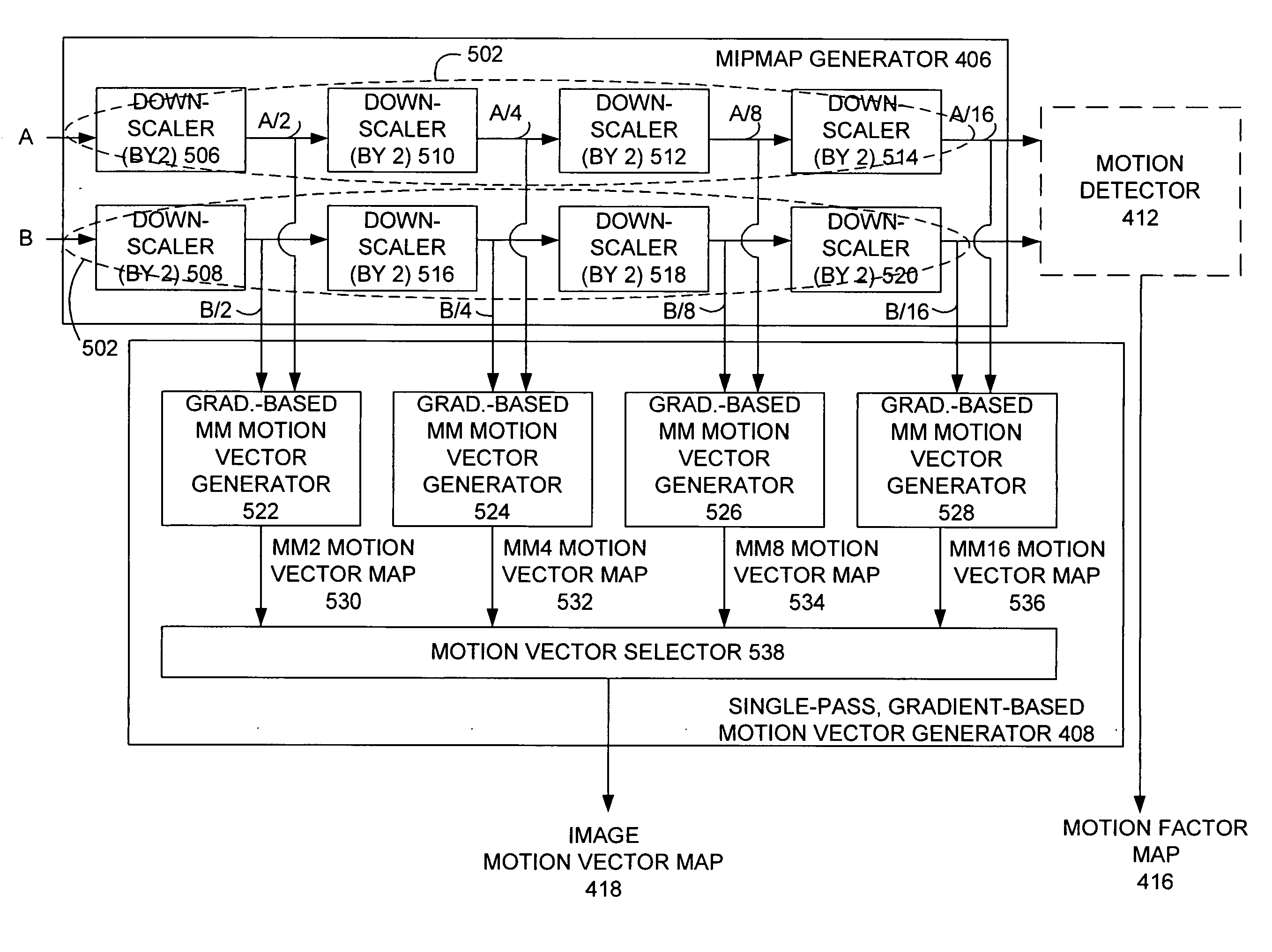
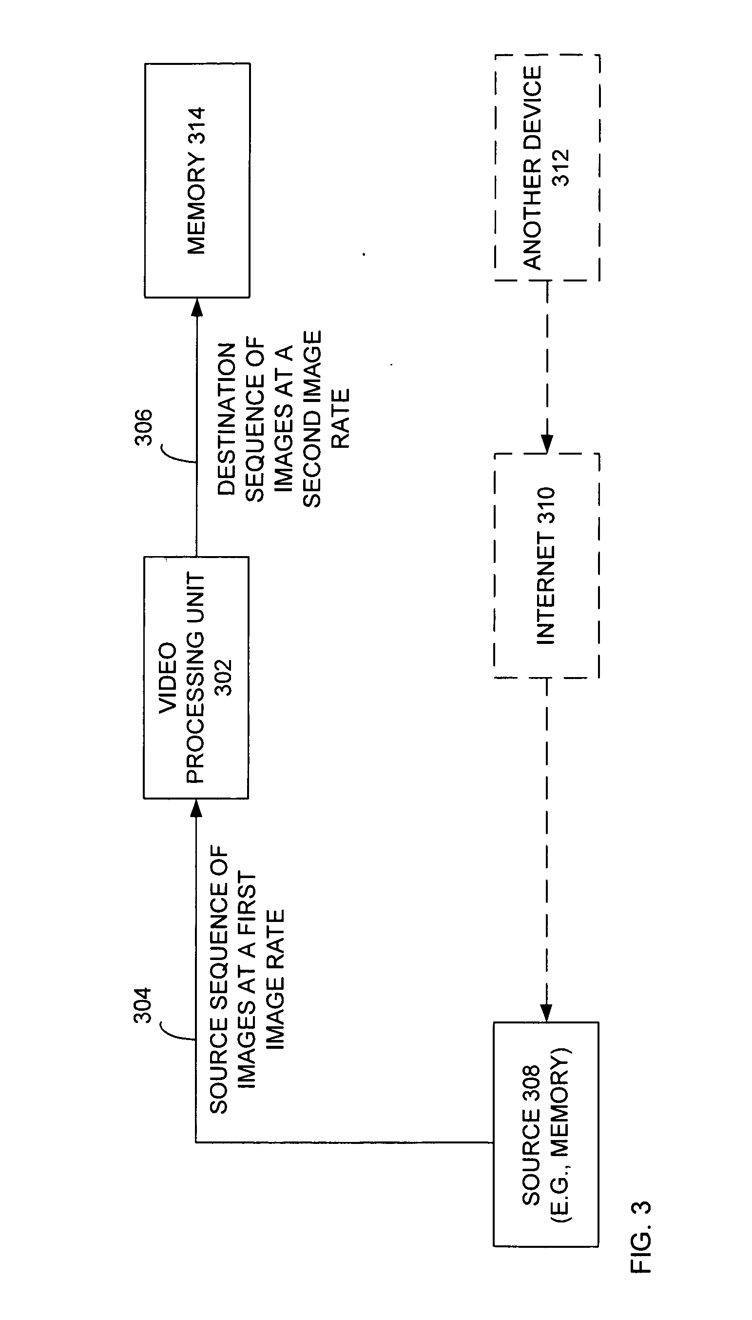
[0023]Generally, one embodiment of the present disclosure provides an integrated circuit that has a mipmap generator, a single-pass gradient-based motion vector generator and an image interpolator for use in generating an interpolated image based on the first and second source image. The mipmap generator generates pairs of mipmaps that each are of a lower resolution that its respective source image. The single-pass, gradient-based motion vector generator generates an image motion vector map having values that represent the motion trajectories for pixels in the first and second source images. Lastly, the image interpolator generates the interpolated image based on the source images and the image motion vector map. In one embodiment, the interpolated image may be used as an upconverted image in a destination sequence of images. In one embodiment, the mipmap generator is not part of the integrated circuit. In another embodiment, the image interpolator is not part of the integrated circ...


PUM


Abstract

A mipmap generator generates pairs of mipmaps that are each of a lower resolution that its respective source image. A single-pass, gradient-based motion vector generator generates an image motion vector map having values that represent the motion trajectories for pixels in the first and second source images. An image interpolator generates an interpolated image based on the source images and the image motion vector map. A motion detector generates a motion factor map based on a pair of mipmaps from those generated by the mipmap generator that represents a detected degree of motion between the first and second source images. The blending module generates a blended, upconverted new image using the motion factor map, the interpolated image and one of the first and second motion maps.

Description

FIELD OF THE INVENTION[0001]The present disclosure generally relates to image rate conversion, and more particularly, to motion compensation image rate upconversion.BACKGROUND OF THE INVENTION[0002]It is known to use a variety of devices to display images to a user. As used herein, an image may be a field (e.g., such as in the context of an interlaced image) or a frame (such as in the context of a deinterlaced or progressive image). Televisions, media players (e.g., DVD players), computing devices (e.g., stationary desktop computers), mobile devices (e.g., cellular phones, personal digital assistants, etc.) are each capable of displaying sequences of images (video and / or graphics) to a user. In the context of video, image sequences are generally created using a fixed image rate (a.k.a. frame or field rate, when dealing with frames or fields, specifically). For example, many telecine processes record video (e.g., movies) in real time, i.e., having a image (or frame) rate of 24 Hz. Wh...

Claims


Application Information

Patent Timeline
IPC IPC(8): G09G5/00H04N5/14
CPCG09G5/00G09G5/14H04N7/014G09G2340/0407G09G2340/10G09G2320/106
Inventor WEI, JEFF X.
Owner ATI TECH INC
Why Eureka
Try Eureka