Multiple-view directional display

a directional display and multi-view technology, applied in the field of multi-view directional display, can solve the problems of increasing the cost, occupying a lot of space, and requiring a separate display screen for each player, and achieve the effect of improving the quality of the display and reducing the angular exten

Active Publication Date: 2009-07-02
SHARP KK
View PDF7 Cites 31 Cited by
  • Summary
  • Abstract
  • Description
  • Claims
  • Application Information

AI Technical Summary

Benefits of technology

[0026]A first aspect of the present invention provides a multiple view directional display comprising: a pixellated image display layer having a plurality of first pixels assigned to display a first image and a plurality of second pixels assigned to display a second image; and a parallax barrier aperture array for directing light from the first pixels generally into a first viewing window and for directing light from the second pixels generally into a second viewing window not overlapping the first viewing window; wherein the display further comprises first light-directing means for re-directing light emitted from a first lateral edge region of each first pixel away from the second viewing window. Provision of the light-directing means allows the image mixing region seen by an observer to be reduced in angular extent or even completely eliminated, thereby improving the quality of the display.

Problems solved by technology

These conflicting needs could be satisfied by providing two separate display devices, but this would take up extra space and would increase the cost.
However, providing a separate display screen for each player takes up a lot of space and is costly, and is not practical for portable games.
However, the two images displayed on an autostereoscopic display are the left-eye and right-eye images of a stereoscopic image pair, and so are not independent from one another.
However, in practice having apertures in the form of slits of only infinitesimal width through which light can pass will not provide a useable brightness for the display.
In addition, light which passes through narrow apertures will be diffracted, and this light could cause unwanted crosstalk even in positions where geometrically one should not see any crosstalk.
It is possible to increase the brightness of the display by increasing the width of the apertures of the parallax barrier 21, however the increase in brightness is at a cost of reduced viewing freedom.
Additionally, if the opaque regions of the parallax barrier are made of a material which is not completely absorbing then light from the pixels can leak into the wrong viewing window and add to the unwanted crosstalk.
However in practice it may be difficult to achieve this performance for several reasons.
The lenses may not be perfectly formed in manufacture, the mechanical stability of the display with thin lenses may suffer, and thermal expansion of the lenses might cause a mismatch in alignment with the pixels.

Method used


Image

  • Multiple-view directional display
  • Multiple-view directional display
  • Multiple-view directional display

Examples


Embodiment Construction

[0079]The invention will be described with reference to a dual view display, intended to display a first image to a first observer and a second image to a second observer. However, the invention may also be applied to an autostereoscopic 3-D display.

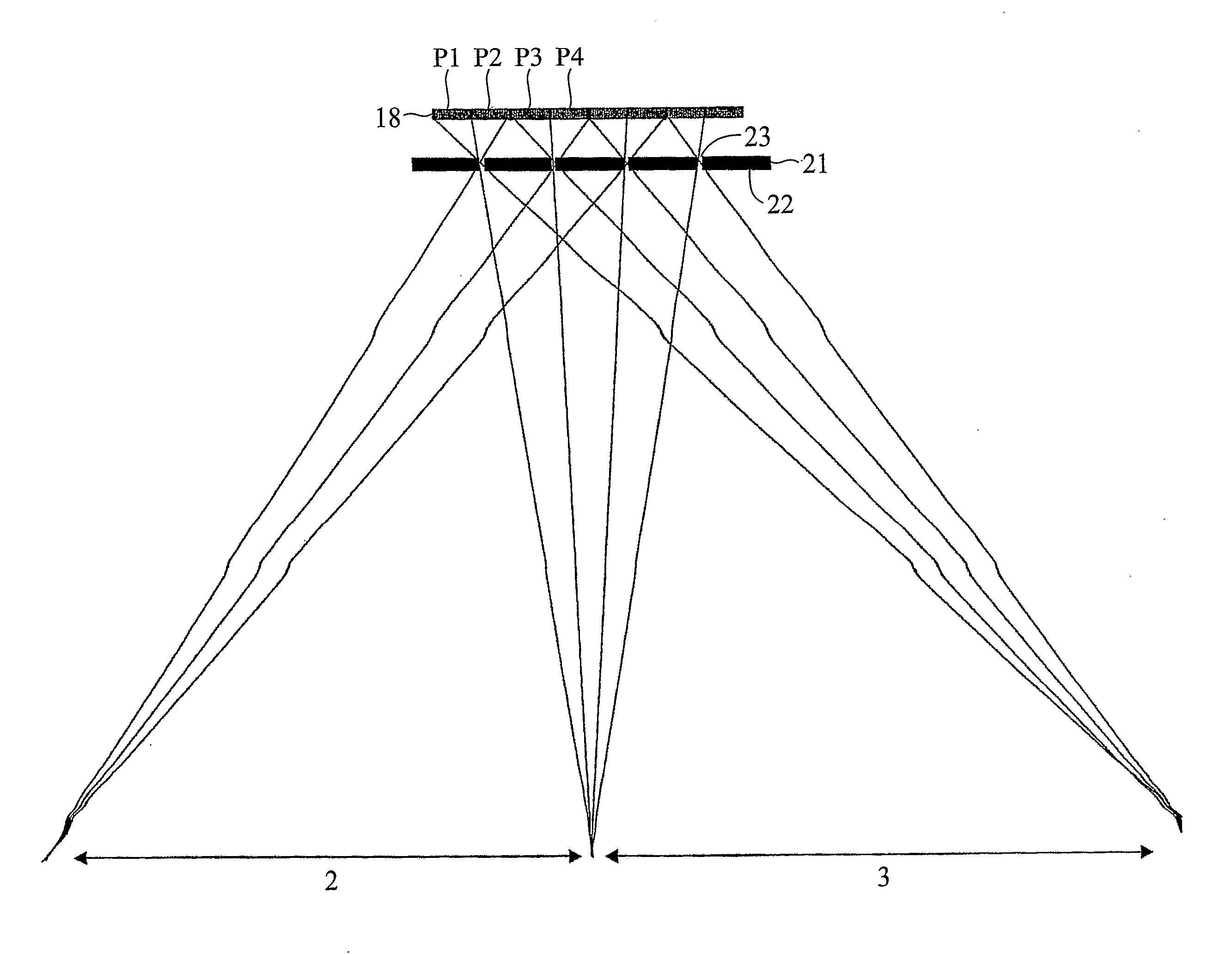
[0080]FIG. 5 shows a dual view display having a pixellated image display layer 8, for example a liquid crystal layer, and a parallax barrier aperture array 21. The pixels are assigned alternately to a “left image” intended for display into a left viewing window 2 and to a “right image” intended for display into a right viewing window 3. Thus, pixels in odd-numbered pixel columns P1, P3 etc are assigned to the left image and so will be referred to as “left pixels” and pixels in even-numbered pixel columns P2, P4 etc are assigned to the right image and so will be referred to as “right pixels”. The apertures 23 of the parallax barrier aperture array have a finite width w so that, as explained with reference to FIG. 4 above, a central image ...


PUM


Abstract

A multiple view directional display comprises a pixellated image display layer having a plurality of first pixels (P1) assigned to display a first image and a plurality of second pixels (P2) assigned to display a second image, and a parallax barrier aperture array (21) for directing light from the first pixels generally into a first viewing window (2) and for directing light from the second pixels generally into a second viewing window (3) not overlapping the first viewing window. The display further comprises first light directing means (31) for re-directing light emitted from a first lateral edge region (25) of each first pixel away from the second viewing window.

Description

TECHNICAL FIELD[0001]The present invention relates to a multiple-view directional display, which displays two or more images such that each image is visible from a different direction. Thus, two observers who view the display from different directions will see different images to cone another. Such a display may be used as, for example, an autostereoscopic display device or a dual view display device.BACKGROUND ART[0002]For many years conventional display devices have been designed to be viewed by multiple users simultaneously. The display properties of the display device are made such that viewers can see the same good image quality from different angles with respect to the display. This is effective in applications where many users require the same information from the display—such as, for example, displays of departure information at airports and railway stations. However, there are many applications where it would be desirable for individual users to be able to see different inf...

Claims


Application Information

Patent Timeline
Patent Type & Authority Applications(United States)
IPC IPC(8): G02B27/26G02B27/22G02B30/25G02B30/30G09F19/14H04N13/00
CPCG02B27/2214G09F19/14H04N13/0447H04N13/0422H04N13/0409H04N13/324H04N13/31H04N13/351G02B30/30G02B30/27
Inventor KEAN, DIANA ULRICHMATHER, JONATHAN
Owner SHARP KK
Why Eureka
Try Eureka