Modulation and demodulation method, modulation apparatus and demodulation apparatus

a modulation apparatus and demodulation method technology, applied in the direction of phase-modulated carrier systems, amplitude demodulation, pulse conversion, etc., can solve the problems of poor error rate, poor configuration error rate, and inability to improve error rate, so as to achieve the effect of minimizing the error ra

Inactive Publication Date: 2009-07-02
NEC CORP
View PDF4 Cites 10 Cited by
  • Summary
  • Abstract
  • Description
  • Claims
  • Application Information

AI Technical Summary

Benefits of technology

[0018]The present invention is made in view of the problems that the conventional techniques described above have. It is an object to provide a modulation and demodulation method, a modulation apparatus and a demodulation apparatus that minimizes an error rate and can be applied to a differential operation modulo 4.

Problems solved by technology

However, an error rate is not good in the configuration.
An error rate cannot be improved unless an error correction coding is applied thereto.
However, an error rate is not good.
An error rate cannot be improved unless an error correction coding is applied thereto.
In addition, these types of mapping are not suitable for application of another simple error correction coding.
Therefore, it is impossible to apply a differential encoding against 90-degree phase uncertainty of a reproduced carrier wave thereto.
Thus, it is impossible to improve the error rate.
Further, since it is the mapping that generates 3 bits or 4 bits of the bit error per 1 symbol error, it is hard to say that bit errors per 1 symbol error can be made as small as possible.
Thus, there is a problem that only one bit can be caused to pass through with respect to drawing phases of 0 degree and 180 degrees of uncertainty of four phases, but all signals cannot necessarily be caused to pass thorough with respect to phase uncertainty of 90 degrees and 270 degrees.

Method used


Image

  • Modulation and demodulation method, modulation apparatus and demodulation apparatus
  • Modulation and demodulation method, modulation apparatus and demodulation apparatus
  • Modulation and demodulation method, modulation apparatus and demodulation apparatus

Examples


Embodiment Construction

[0049]An embodiment of the present invention will now be described with reference to the drawings.

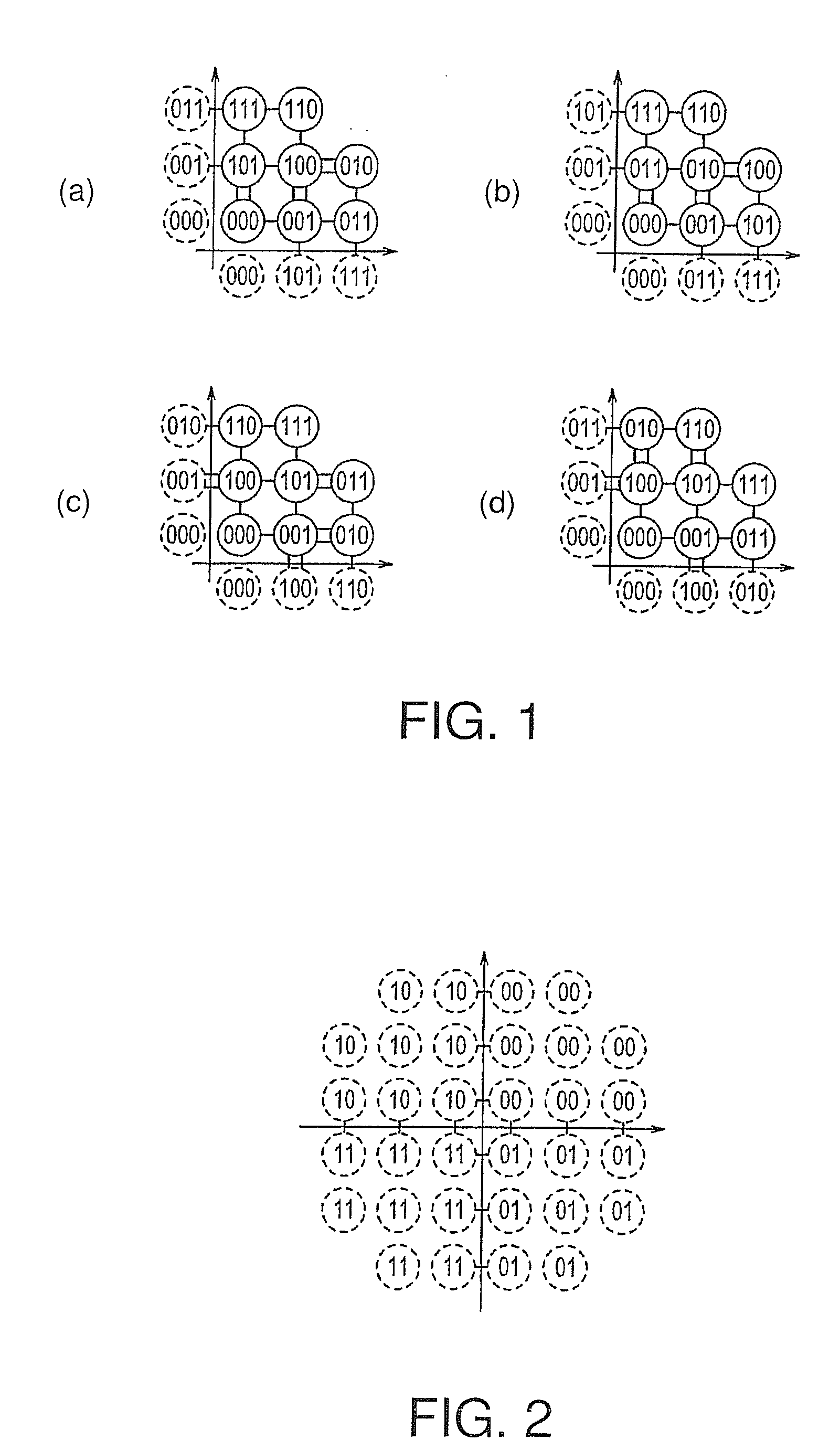
[0050]FIG. 1 is a diagram illustrating mapping in which an average Hamming distance between subgroups is minimized according to an embodiment of a modulation and demodulation method of the present invention. There are four kinds of mapping for minimizing the average Hamming distance between subgroups. In this regard, another mapping for minimizing the average Hamming distance can be created by arbitrarily replacing 3 bits of the mapping shown in FIG. 1 with each other or by adding 1 to an arbitrary bit of the 3 bits with exclusive OR.

[0051]As shown in FIG. 1, in the modulation and demodulation method of the present invention, signal points (circle signs in the figure) arranged in a first quadrant of four quadrants, which are divided by in-phase and orthogonal axes that are perpendicular to each other, are divided into 8 subgroups corresponding to 3 bits of input data. Here, it indicates...


PUM


Abstract

The present invention relates to a modulation and demodulation method of minimizing an error rate and applying it to a differential operation modulo 4. A modulation apparatus includes a Gray coding circuit 101 to which data of (2n+1) bits are inputted (where “n” is an integer more than 1) and which encodes 2 bits of an input signal of (2n+1) bits to a Gray code as a signal for allowing four quadrants to be identified, an encoding circuit 102 that encodes 3 bits of the input signal of (2n+1) bits as a signal indicating any one of eight subgroups provided in each of the four quadrants so that an average Hamming distance between adjacent subgroups within its quadrant becomes a minimum, and a mapping circuit 104 that maps binary data encoded by the Gray coding circuit 101 and the encoding circuit 102 on the four quadrants.

Description

TECHNICAL FIELD[0001]The present invention relates to a modulation and demodulation method, a modulation apparatus and a demodulation apparatus, and particularly, the present invention relates to a multilevel quadrature amplitude modulation and demodulation method, a modulation apparatus and a demodulation apparatus in which 22n+1 is provided as a multilevel value (where “n” is an integer more than 1).BACKGROUND ART[0002]Heretofore, modulation and demodulation systems of 32 Quadrature Amplitude Modulation (QAM) and 128 QAM have been adopted in a digital microwave communication system. Further, application of the 32 QAM system has been mainly suggested in a mobile communication system. There is an example in which the 32 QAM is described for standardization as a modulation element of adaptive modulation and coding. Moreover, there is also a standard utilizing the 32 QAM in digital video broadcasting (DVB).[0003]As such a modulation and demodulation system, for example, Japanese Paten...

Claims


Application Information

Patent Timeline
Patent Type & Authority Applications(United States)
IPC IPC(8): H04L25/49
CPCH04L25/067H04L27/3405H04L27/3488
Inventor NODA, SEIICHISASAKI, EISAKU
Owner NEC CORP
Why Eureka
Try Eureka