Motion-oriented image compensating method

a compensation method and image technology, applied in the field of image compensation, can solve the problems of largely degrading image quality, image captured would get blurred, image output from conventional digital cameras are still quite blurred, etc., and achieve the effect of effectively promoting image quality, sharpness of image edges, and promoting image sharpness

Inactive Publication Date: 2009-07-02
WINBOND ELECTRONICS CORP
View PDF6 Cites 2 Cited by
  • Summary
  • Abstract
  • Description
  • Claims
  • Application Information

AI Technical Summary

Benefits of technology

[0008]Accordingly, the present invention is directed to a motion-oriented image compensating method, which is suitable for promoting the edge sharpness of an edge containing motion objects and the edge sharpness of an edge photographed by a shaking video camera so as to enhance the image quality.
[0009]The present invention is also directed to a motion-oriented image compensating method, which is able to conduct image compensation based on the motion trajectory of images to effectively promote the edge sharpness of an image so as to enhance the image quality.
[0012]The present invention uses the pixel luminance of the present image data and the last image data to extract the minimum motion vector in X-axis of the present image data (horizontal motion vector) and the minimum motion vector in Y-axis of the present image data (vertical motion vector) and then conducts luminance compensation of pixels according to the above-mentioned two minimum motion vectors so as to promote the sharpness of image edges. In other words, the present invention conducts image compensation according to the motion trajectory of an image; thus, regardless an image containing a moving object, or an image photographed by a shaking video camera, the sharpness of image edges and the image quality are able to be effectively promoted by using the method of the present invention.

Problems solved by technology

It is well known that when a motion object is photographed or taking a picture with a shaking camera, the image captured would get blurred.
Even though by using a conventional digital camera equipped with a digital image stabilization (DIS) system where the DIS is employed to stabilize the image sequence by means of moving pixel scheme (i.e. a so-called anti-shake function), the images output from the conventional digital camera are still quite blurred, which largely degrades the image quality.
Although the proposed approach is able to effectively stabilize an image sequence, but it fails to compensate the blur portion of an image. FIG. 1 is a block diagram of a conventional digital image stabilization (DIS) system.
One thing is for sure that the above-mentioned scheme still fails to improve the sharpness of image edges.
In addition, the above-mentioned scheme would cause a new problem that a blur image edge caused by taking a picture with trembling hands reduces the accuracy of the LMVs obtained by using the edge pattern matching. FIG. 2 is a block diagram of another conventional digital image stabilization (DIS) system.
It is clear from FIG. 3, the compensations of the above-mentioned approach are not based on the motion trajectory of images, therefore, and the approach only provides a very limited effect of improving sharpness and fails to effectively advance image quality.

Method used


Image

  • Motion-oriented image compensating method
  • Motion-oriented image compensating method
  • Motion-oriented image compensating method

Examples


Embodiment Construction

[0020]Reference will now be made in detail to the present preferred embodiments of the invention, examples of which are illustrated in the accompanying drawings. Wherever possible, the same reference numbers are used in the drawings and the description to refer to the same or like parts.

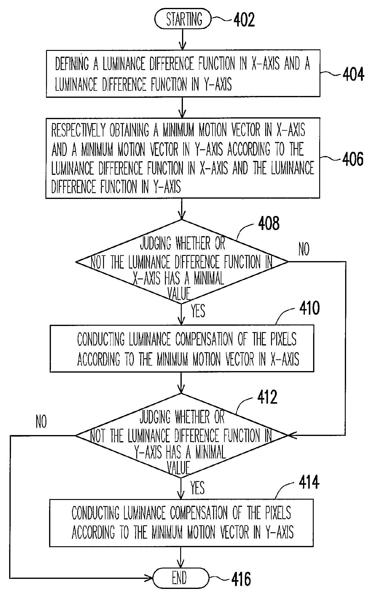
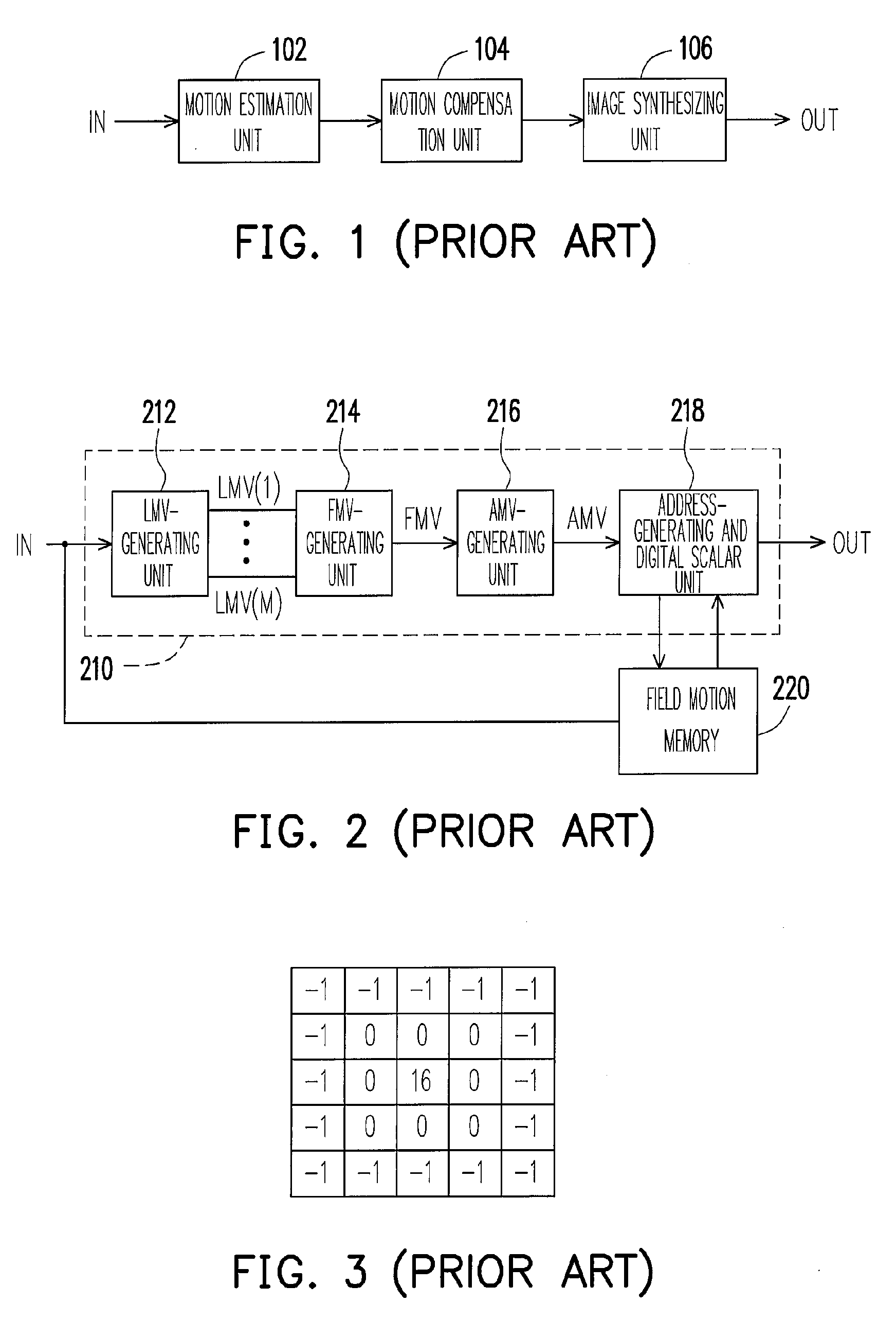
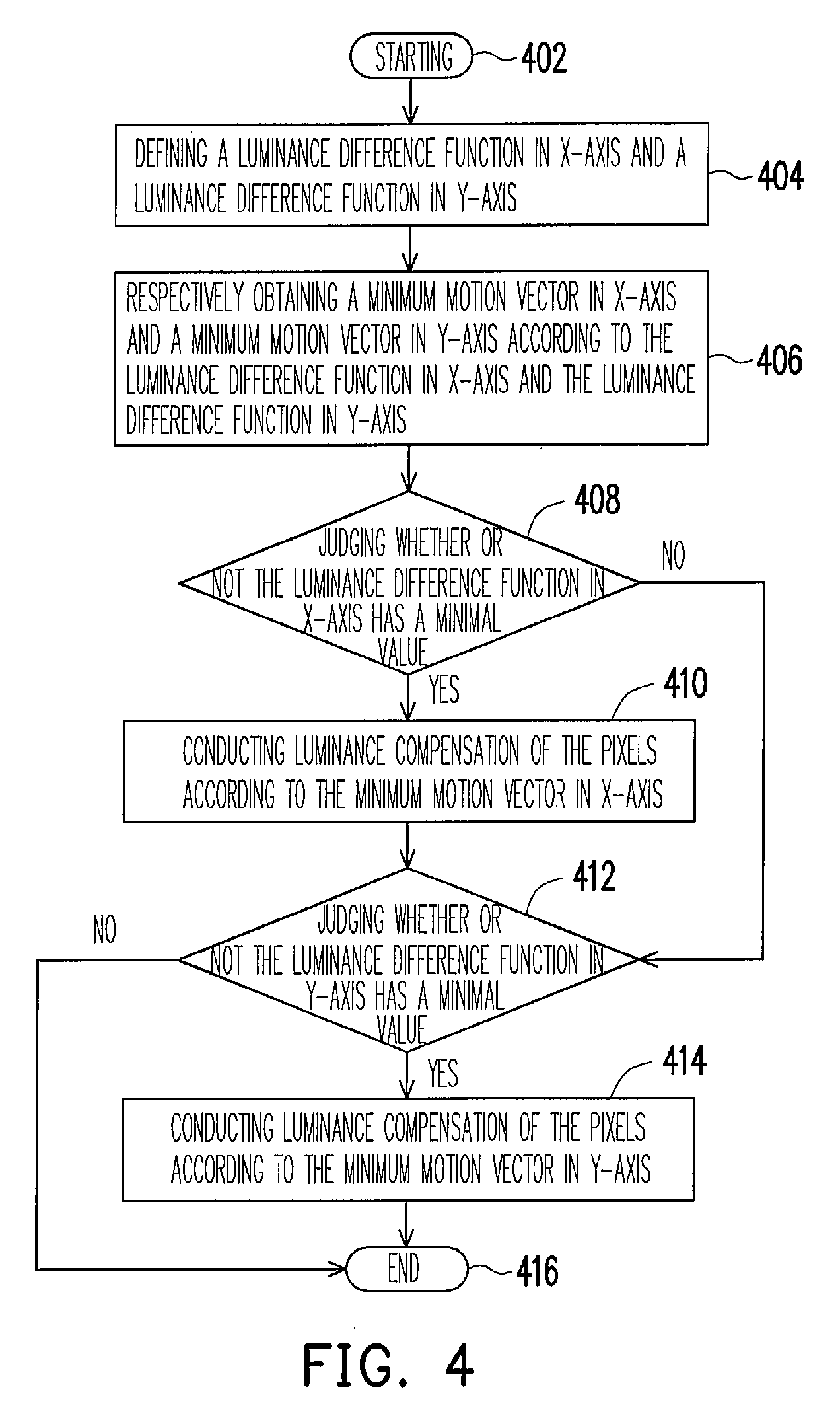
[0021]In the following, a motion-oriented image compensating method is described, which is suitable to sharpen the image edges generated by an image data with a resolution of M×N pixels, wherein M and N are natural numbers. In order to calculate global motion vectors (including horizontal motion vector and vertical motion vector) between the present frame and the last frame available for further conducting image compensation, a motion estimation approach must be introduced first. A DIS system then would shift the pixels of the present image to stabilize the image sequence. In addition, to obtain instant global motion vectors, a color-based motion estimation scheme employed. In the following, the imag...


PUM


Abstract

A motion-oriented image compensating method is disclosed. The method uses the pixel luminance of a present image data and a last image data to judge the minimum motion vector in X-axis and the minimum motion vector in Y-axis of the present image data, following by conducting luminance compensation of the pixels according to the above-mentioned two minimum motion vectors to advance the sharpness of image edges and thereby the image quality.

Description

BACKGROUND OF THE INVENTION[0001]1. Field of the Invention[0002]The present invention generally relates to an image compensating method, and more particularly, to a motion-oriented image compensating method.[0003]2. Description of Related Art[0004]It is well known that when a motion object is photographed or taking a picture with a shaking camera, the image captured would get blurred. Even though by using a conventional digital camera equipped with a digital image stabilization (DIS) system where the DIS is employed to stabilize the image sequence by means of moving pixel scheme (i.e. a so-called anti-shake function), the images output from the conventional digital camera are still quite blurred, which largely degrades the image quality.[0005]In 2003, Institute of Electrical and Electronics Engineers (IEEE) held an international conference with a subject title of “Advanced Video and Signal Based Surveillance” in Miami, USA, wherein a paper of “Color-based Video Stabilization for Rea...

Claims


Application Information

Patent Timeline
Patent Type & Authority Applications(United States)
IPC IPC(8): G06K9/00
CPCG06T2207/10016G06T2207/20201H04N5/23248G06T2207/20192H04N5/23267G06T5/003H04N5/23254H04N23/68H04N23/6811H04N23/683
Inventor CHIU, SHANG-KAI
Owner WINBOND ELECTRONICS CORP
Why Eureka
Try Eureka