
Scanning brush and method of use

a scanning brush and scanning method technology, applied in the field of scanning brush and scanning method, can solve the problems of reducing the sharpness at the edges of the image, affecting the accuracy of integrated circuit applications, and affecting the accuracy of scanning beams, so as to improve the sharpness of scanning lines, avoid skew, and minimize the effect of scanning line bow

Inactive Publication Date: 2005-05-24
APPLIED MATERIALS INC
View PDF7 Cites 0 Cited by
  • Summary
  • Abstract
  • Description
  • Claims
  • Application Information

AI Technical Summary

Benefits of technology

[0014]In accordance with the invention, a multi-beam scanner has a wide scan brush, a modulator that controls intensity of pixels in scan beams, an optical system that minimizes scan line bow at the expense of non-uniform scanning beam velocity, and a timing generator that generates a pixel clock signal having a variable period that compensates for the non-uniformity of pixel velocity. The wide separation of scan beams permits the modulator to turn beams on or off with a direction of brightening or darkening in the cross-section of the beams being opposite to the scanning direction. This allows the brightening direction to be opposite the scan direction to improve edge sharpness, avoid skew in rectangular regions, and avoid a directional bias in line thickness.
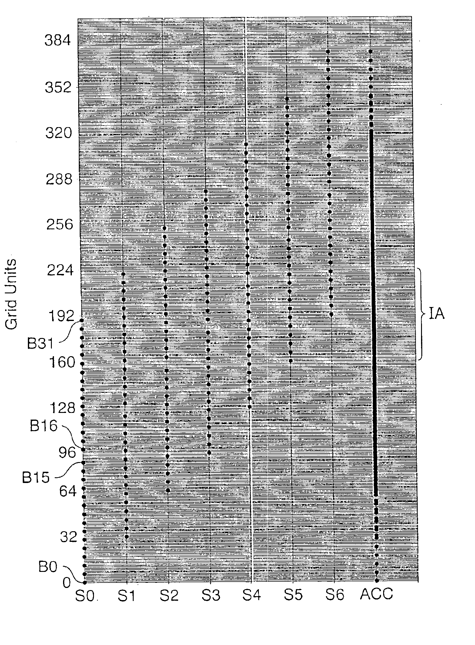
[0015]A novel arrangement of the beams in the brush permits a uniform indexing step size to uniformly expose an image region. In particular, a brush with b beams spaced a distance n apart uniformly covers the image region after repeated scanning and indexing by a distance m if the number of beams b and the distances n and m are such that the ratio of m to n is equal to the ratio of b to an integer q that has no common factors with b. In one embodiment, a diastemal brush has a top half including b beams uniformly spaced distance n apart and a bottom half including b beams uniformly spaced distance n apart. The distance between the top and bottom halves is 1.5*n. With this diastemal brush and a uniform indexing distance m, the top half forms uniformly spaced scan lines, and the bottom half forms scan lines midway between adjacent scan lines that the top half forms. Other embodiments of the scan bush include three or more sections of equal spaced beams separated by two or more diastema.

Problems solved by technology

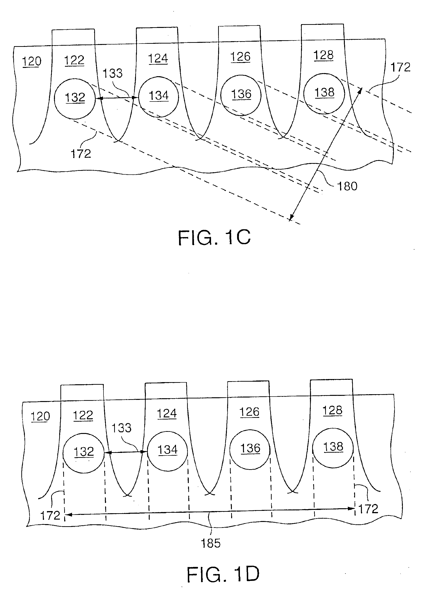
As indicated above, disadvantages of the configuration of FIG. 1C are reduced sharpness at the edges in the image, skew of rectangular areas, and 45° / 135° line thickness bias.
This creates a scan brush that is wider than the brush of FIG. 1C, and the wider scan brush increases scan line bow from a conventional f-θ scan lens, making the accuracy required for integrated circuit applications difficult to achieve.
Other types of scan lenses can reduce scan line bow but generally cause scan beams to move with non-uniform velocity and therefore can distort the image.

Method used


Image

  • Scanning brush and method of use
  • Scanning brush and method of use
  • Scanning brush and method of use

Examples


Embodiment Construction

[0025]In accordance with an aspect of the invention, a precision printing system employs a scanner and multiple scan beams arranged in a wide scan brush with separations between individual beams. An acousto-optic modulator or deflector in the printing system controls the intensities of individual scan beams using acoustic waves oriented along the scan direction. Accordingly, as the acousto-optic modulator turns a beam on or off, successive portions of a scan beam cross-section brighten or darken along the direction of propagation of the scan lines. The printing system uses a scan lens such as an f-sin θ scan lens that reduces scan line bow caused by the width of the scan brush, and a timing generator that generates a pixel clock signal with a variable period to compensate for variations in the velocity of scan beams.

[0026]FIG. 2 shows a precision printing system 200 that employs scanning in accordance with an embodiment of the invention. A pre-scan portion of system 200 includes a b...


PUM

PropertyMeasurementUnit
poweraaaaaaaaaa
sizeaaaaaaaaaa
sizeaaaaaaaaaa

Abstract

A scanning system uses a multi-beam brush having a widely separated beams, a modulator that controls intensity of pixels in scan beams, an optical system that minimizes scan line bow at the expense of non-uniform scanning beam velocity, and a timing generator that generates a pixel clock signal having a variable period that compensates for the non-uniformity of pixel velocity. The wide separation of scan beams permits the modulator to turn beams on or off with a direction of brightening or darkening in the cross-section of the beams being opposite to the scanning direction. A novel arrangement of the beams in the brush permits a uniform indexing step size to uniformly expose an image region. In one embodiment, the timing generator includes: a source of pixel period values; a select circuit to select pixel period values for pixels, and a counter that loads a first value from the pixel period value selected for a pixel, counts for a period of time indicated by the first value, and asserts a signal marking an end of the period. An additional delay after the signal from the counter can be shorter than the period of a clock signal to the counter but also controlled by the pixel period value.

Description

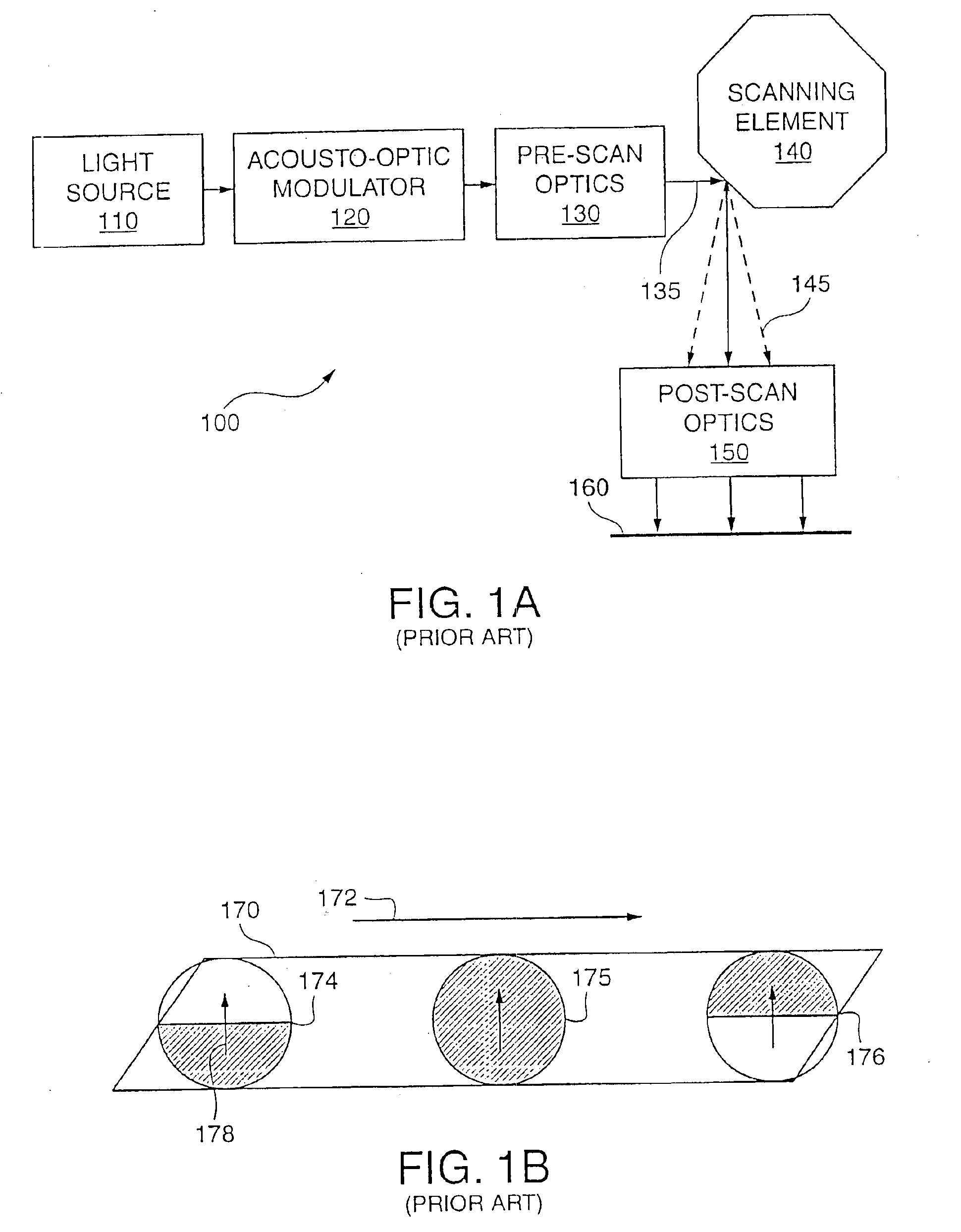
CROSS REFERENCE TO RELATED APPLICATION[0001]This application is a divisional application of application Ser. No. 09 / 273,115, filed Mar. 19, 1999, now U.S. Pat. No. 6,731,320.[0002]This patent document is related to and incorporates by reference in its entirety, co-filed U.S. patent application Ser. No. 09 / 272,947, entitled “Multi-Beam Scanner Including A Dove Prism Array”.BACKGROUND[0003]1. Field of the Invention[0004]This invention relates to printing systems and methods and particularly systems and methods using multiple scan beams that have wide lateral separations.[0005]2. Description of Related Art[0006]Printing systems including scanners are suitable for a variety of applications including printing text on paper, patterning photoresist during integrated circuit manufacture, and creating masks or reticles for projection-type photolithography systems. For integrated circuit applications, the printing systems typically require submicron precision. FIG. 1A illustrates the basic ar...

Claims


Application Information

Patent Timeline
Patent Type & Authority Patents(United States)
IPC IPC(8): G03F7/20G02B26/10G02F1/33B41J2/44H01L21/027H04N1/113
CPCG03F7/704H04N1/053
Inventor ALLEN, PAUL C.BOHAN, MICHAEL J.GREEN, MORRIS H.HAMAKER, HENRY CHRISTOPHER
Owner APPLIED MATERIALS INC
Learn More