
Method of painting a plastic work piece using an electrostatically isolated mask

a technology of electrostatic isolation and workpiece, which is applied in the direction of liquid surface applicators, spraying apparatus, pretreated surfaces, etc., can solve the problems of undesirable aesthetics of the final product, poor consistency of the process, and low transfer efficiency, so as to improve the aesthetics of the workpiece, and reduce the effect of spherical distortion

Active Publication Date: 2017-05-18
LACKS ENTERPRISES
View PDF2 Cites 1 Cited by
  • Summary
  • Abstract
  • Description
  • Claims
  • Application Information

AI Technical Summary

Benefits of technology

This patent describes a method for painting plastic work pieces using an electrically conductive material. The method allows for increased paint transfer efficiency and the creation of multi-finishes with minimal paint spray. Various spray patterns can be utilized and atomized clouds can be sprayed near the work piece. This method also improves edge sharpness between paint color variations. A mask is used to prevent the conductive paint from being statically attracted towards the mask, resulting in an increased transfer efficiency of the conductive paint.

Problems solved by technology

However, variations in paint deposition methods have resulted in the aesthetics of the final product being undesirable.
An issue with this masking technique is that it is very labor intensive and the consistency of the process can be poor since the tape is aligned and applied by hand.
The downside to using such masks, however, is that the transfer efficiency, i.e., the percentage of paint that is sprayed and which successfully makes it onto the work piece, can be quite low—sometimes less than 20%.
Metal masks are generally not utilized in electrostatic spray painting operations to provide a two-tone appearance of work pieces because the metal masks are conductive, which can cause a large amount of paint to be attracted to and applied to the mask instead of the work piece.

Method used


Image

  • Method of painting a plastic work piece using an electrostatically isolated mask
  • Method of painting a plastic work piece using an electrostatically isolated mask
  • Method of painting a plastic work piece using an electrostatically isolated mask

Examples


Embodiment Construction

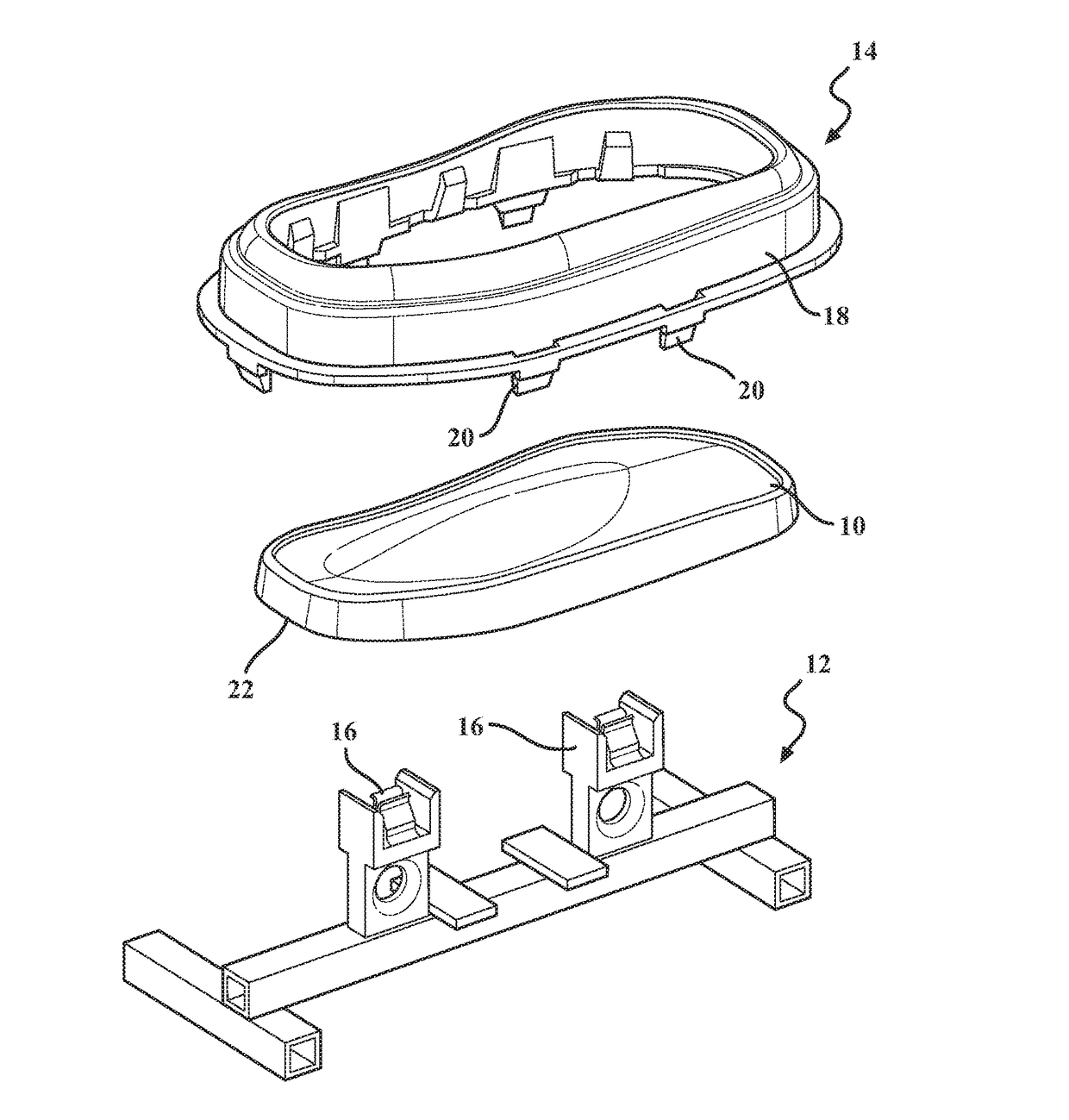
[0024]Referring to the Figures, wherein like numerals indicate corresponding components throughout the several views, methods are generally shown for painting plastic work pieces 10. It should be appreciated that the term “plastic” as used herein encompasses various types of organic polymer materials.

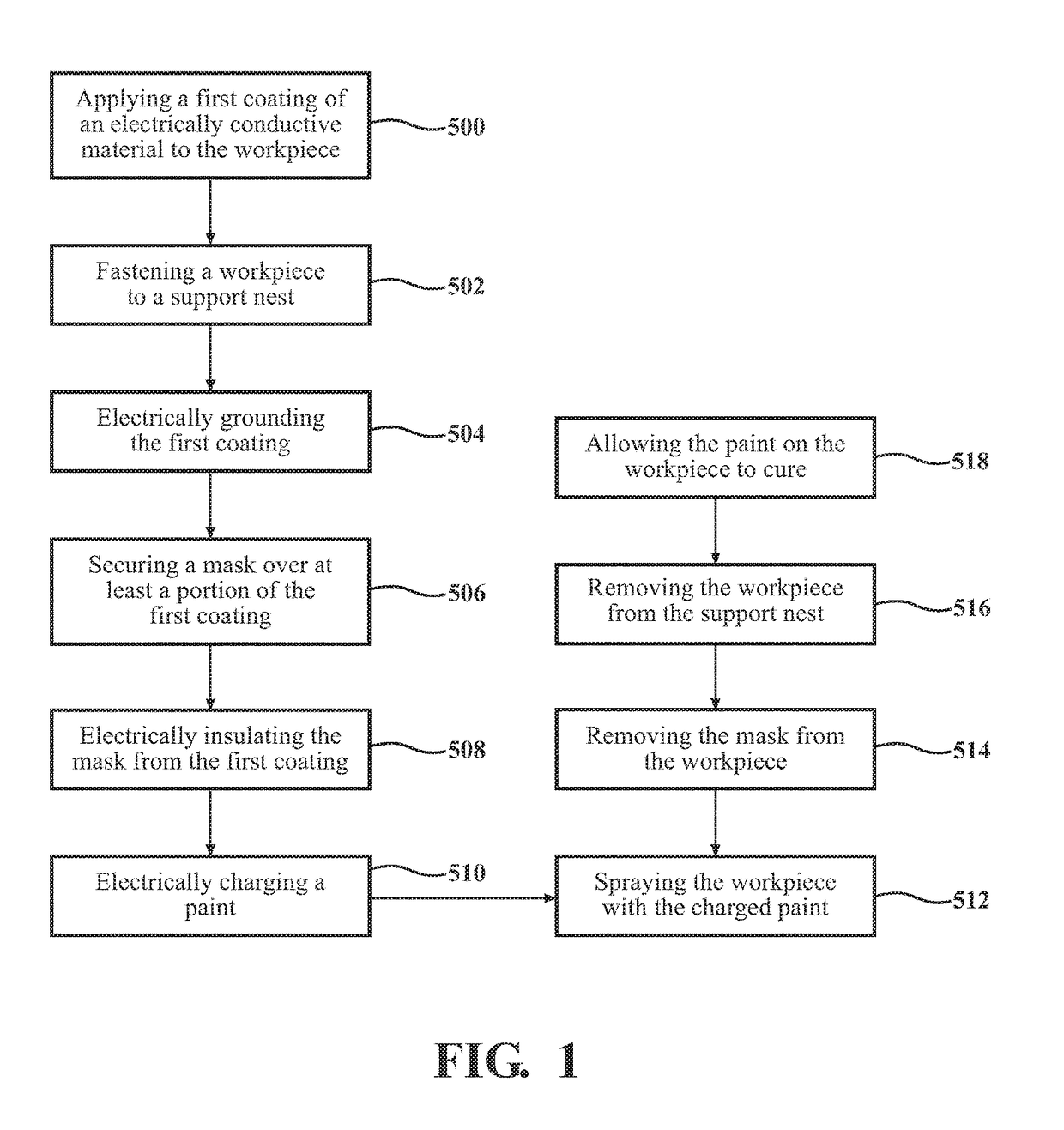
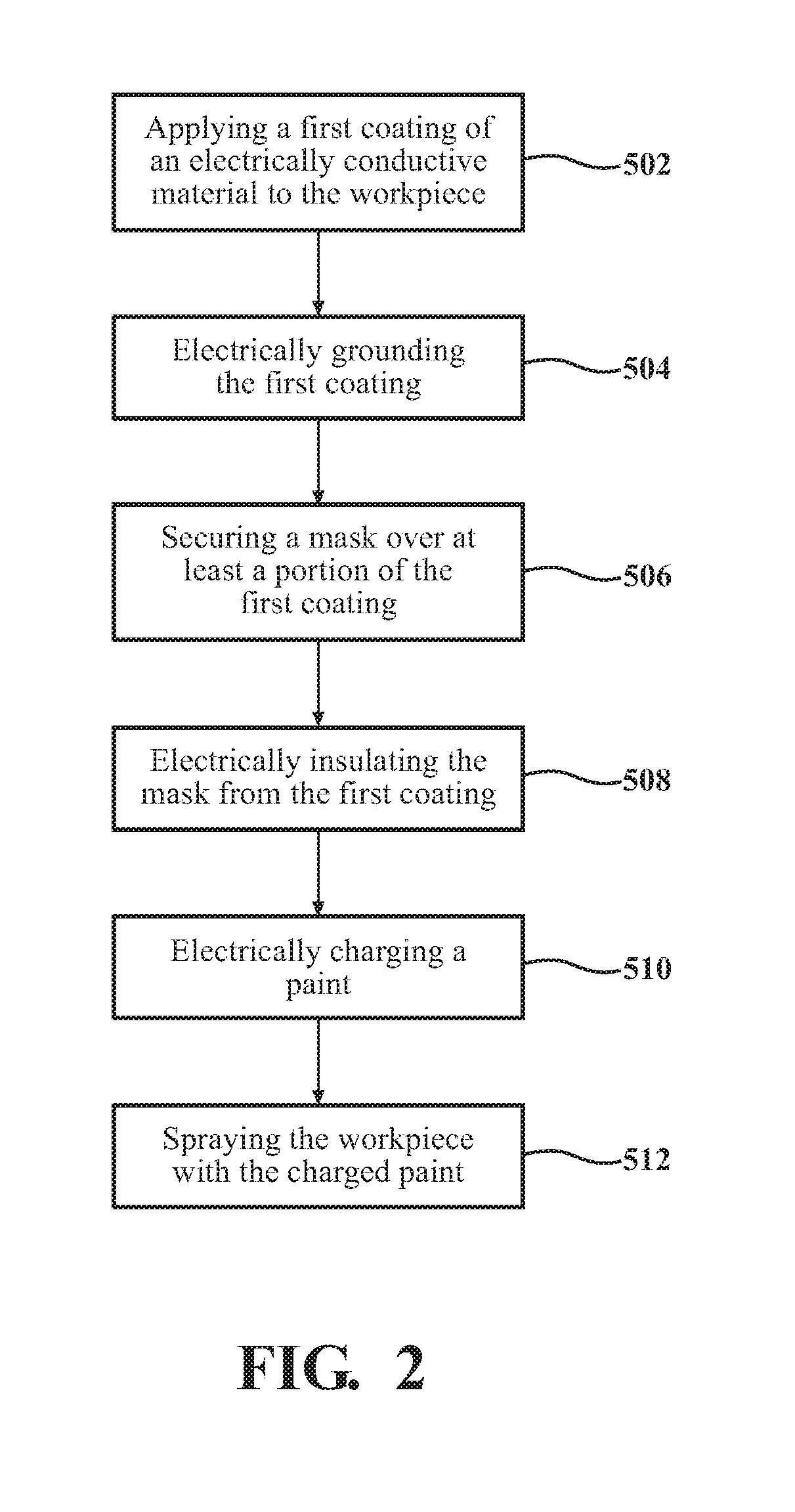
[0025]According to an aspect, as exemplarily shown in FIGS. 1-2, the method generally includes the step 500 of applying a first coating of an electrically conductive material to a work piece 10. According to an aspect, the step 500 of applying the first coating of the electrically conductive material to the work piece 10 may include utilizing an electroplating process, a physical vapor deposition process, a sputtering deposition process, a vacuum metalizing process, adding conductive pigments to the plastic material of the work piece 10, or molding a Mylar film about the work piece. Suitable conductive materials that may be utilized to form the first coating according to the subject met...


PUM


Abstract

A method for painting a work piece of plastic material. The method includes applying a first coating of an electrically conductive material to the work piece and electrically grounding the first coating. The method also includes electrostatically charging a paint to render the paint conductive for statically attracting the conductive paint toward the grounded first coating of the work piece. The method also includes overlying a mask of a non-conductive material over at least a portion of the first coating of the work piece and electrically insulating the mask. The work piece is then sprayed with the conductive paint to apply a layer of paint on the first coating with the mask preventing the conductive paint from being applied on the portions of the first coating of the work piece that are covered by the mask.

Description

CROSS-REFERENCE TO RELATED APPLICATIONS[0001]This U.S. patent application claims the benefit of U.S. Provisional Patent Application Ser. No. 62 / 256,990 filed Nov. 18, 2015, entitled “Method of Painting a Plastic Work Piece Using an Electrostatically Isolated Mask,” the entire disclosure of the application being considered part of the disclosure of this application and hereby incorporated by reference.TECHNICAL FIELD[0002]The present disclosure relates generally to improved aesthetics for plastic work pieces. More specifically, the present disclosure relates to a method of improving the aesthetics of a plastic work piece through the provision of multiple painted finishes.BACKGROUND OF THE DISCLOSURE[0003]Painted decorative finishes have long been available for various products in industries such as the automotive, appliance, consumer electronics, and household application industries. However, variations in paint deposition methods have resulted in the aesthetics of the final product ...

Claims


Application Information

Patent Timeline
IPC IPC(8): B05D1/04B05D3/00B05D1/32
CPCB05D1/04B05D3/007B05D1/322B05D7/02B05D7/52B05D1/045B05D1/32B05B12/20
Inventor CHASE, LEESTUART, SCOTT
Owner LACKS ENTERPRISES
Learn More