Cutter device

a cutting device and cutter technology, applied in the field of cutting devices, can solve the problems of difficult transmission of large torque, time-consuming to obtain target accuracy, cutting failure, etc., and achieve the effect of large torqu

Active Publication Date: 2009-07-02
JAPAN STEEL WORKS LTD
View PDF13 Cites 13 Cited by
  • Summary
  • Abstract
  • Description
  • Claims
  • Application Information

AI Technical Summary

Benefits of technology

[0018]An object of the invention is to provide a cutter device having an aligning function, which can achieve the transmission of large torque.
[0028]According thereto, it is possible to suppress reduction in torque transmission efficiency. In addition, the life of components can be increased.

Problems solved by technology

However, it takes time to obtain target accuracy by the accuracy adjustment.
Accordingly, sometimes, a cutting failure is caused.
However, in the case of the devices disclosed in JP-A-2000-301532 and U.S. Pat. No. 5,624,688, the transmission of large torque is difficult, because the balls are used as torque transmission members.
Further, in the case of the device disclosed in JP-A-2003-326519, the torque transmission members are pins (or shafts), which are more favorable than the balls and are still unsuitable for the transmission of large torque.
Thus, when the transmission of large torque is performed, breakage of the ball and deformation of the pin (or shaft) may occur.
In addition, the related cutter devices described above have problems in that the life of each of these torque transmission members is short, and that the exchange frequency thereof is high.
Thus, the generated dent prevents the ball from moving smoothly.
As a result, the flexible performance is limited.
Thus, the problems of generation of vibrations and impossibility of pelletization may occur.
Accordingly, the structure disclosed in Japanese Patent No. 2642579 is unsuitable for transmission of large torque.
Thus, the transmission of large torque cannot be achieved.
Consequently, a burden is imposed on the pin.
Further, because the rotary torque is received by the line contact between the pin and a pin hole, the device disclosed in JP-A-2003-326519 is unsuitable for transmission of a large force.
Thus, rattling is caused.
Further, vibrations occur due to accuracy failure.
Moreover, pelletizing performance failure and flexibility failure are caused.
Furthermore, cutoff of the pin is caused.
Finally, breakage of the cutter device itself may occur.
Thus, even in the case of the structure disclosed in JP-A-2003-326519, it is difficult to continuingly maintain flexibility and favorably perform pelletizing while large torque is transmitted.
Thus, the related flexible holders utilizing the spherical elements do not have a structure enabling the transmission of large torque.
Therefore, the related flexible holders cannot exercise functions sufficient to meet demands for realizing high-functions of the device and for increasing the size thereof.

Method used


Image

  • Cutter device
  • Cutter device
  • Cutter device

Examples


Embodiment Construction

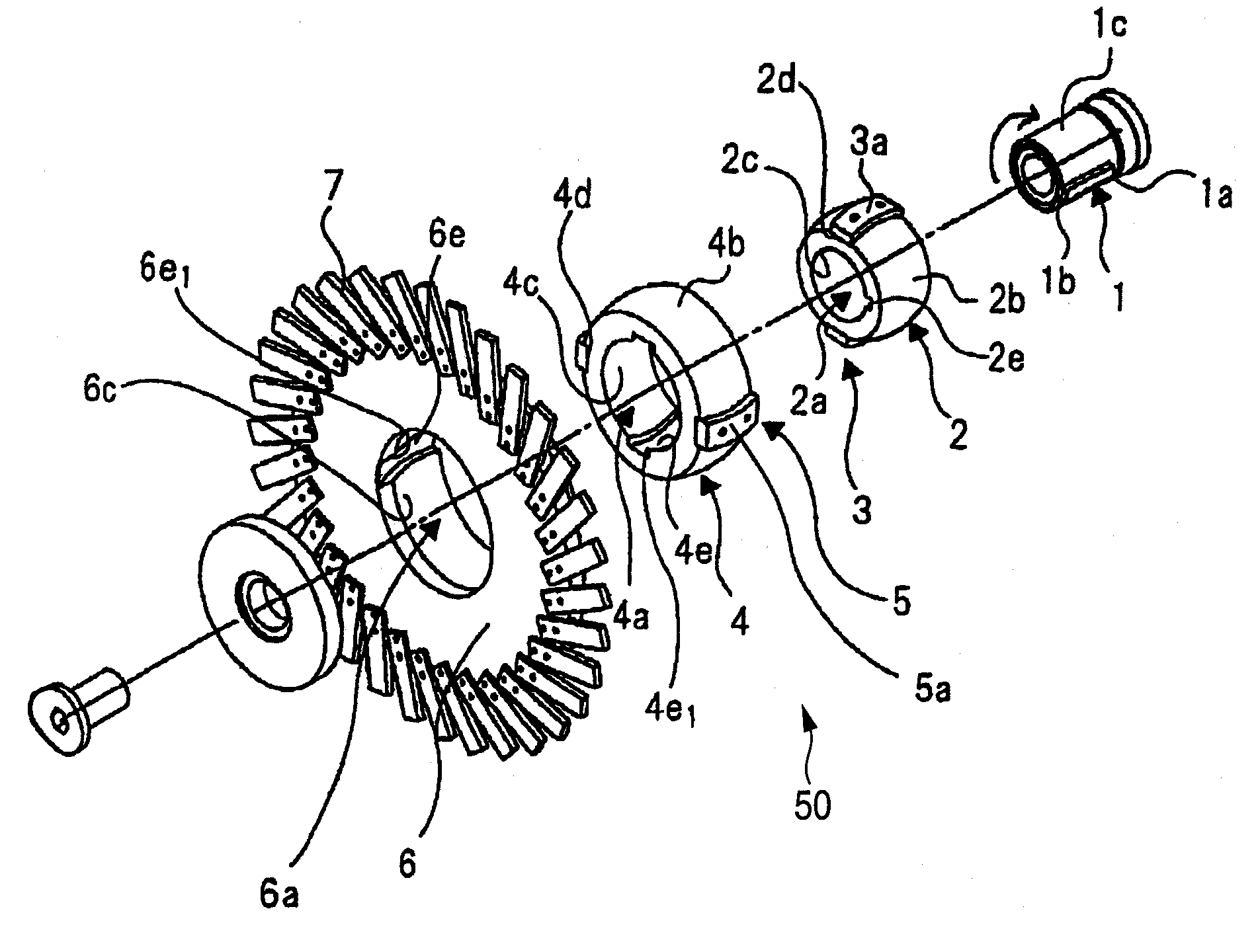
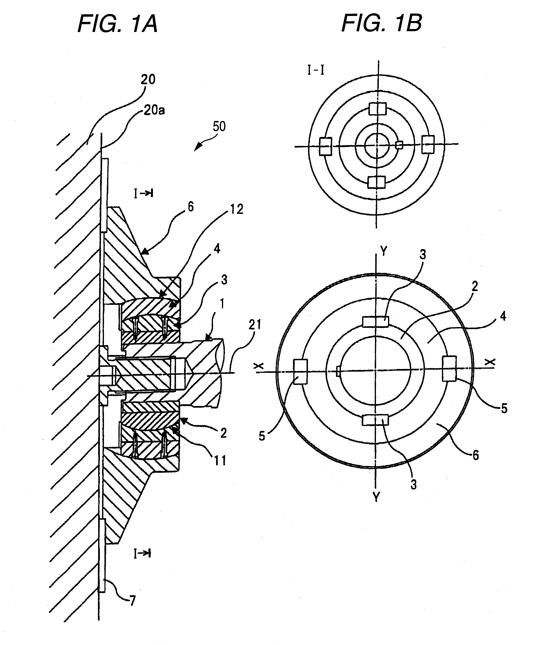
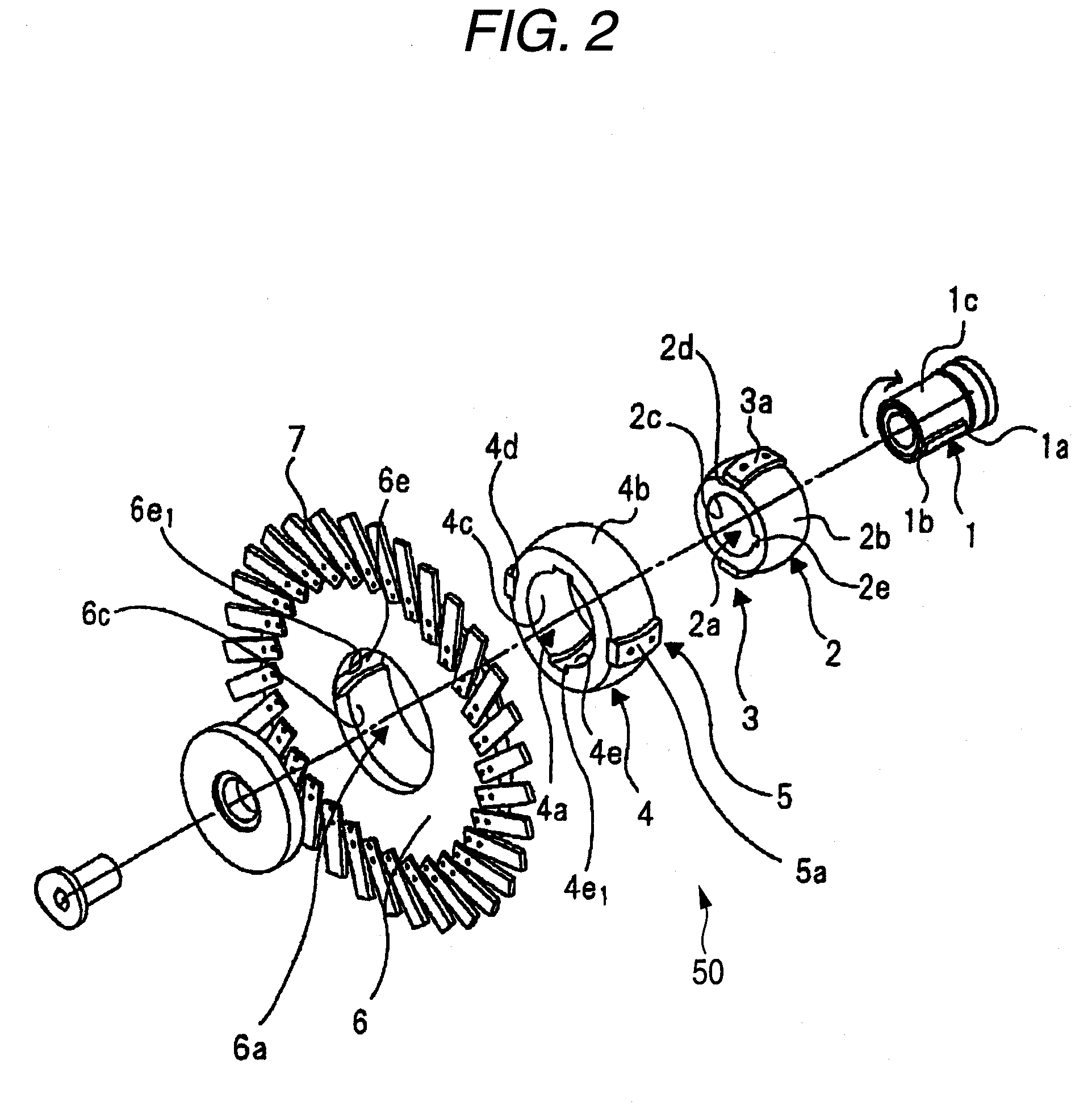
[0045]FIG. 1A illustrates a side cross-sectional view of a cutter device 50 according to the invention. FIG. 1B illustrates a view taken in the direction of arrows I-I shown in FIG. 1A. Further, FIG. 2 illustrates an exploded perspective view of a cutter device 50 according to the invention.

[0046]The cutter device 50 according to the invention includes a driving force transmission mechanism of a spherical structure.

[0047]The driving force transmission mechanism has an aligning function of transmitting a rotation driving force of a cutter shaft 1 to a cutter holder 6. The driving force transmission mechanism includes a fixing holder 2, keys 3, a spherical cylinder 4, and keys 5.

[0048]The structure of each component of the driving force transmission mechanism of the cutter device 50 of the invention will be described below.

[0049]A key groove 1b extending in an axial direction is formed in an outer circumferential surface 1c of the cutter shaft 1. A key 1a is fit into the key groove 1b...


PUM

PropertyMeasurementUnit
frictional coefficientaaaaaaaaaa
rotary torqueaaaaaaaaaa

Abstract

A cutter device includes a fixing holder, a spherical cylinder, and a cutter holder. The fixing holder has a through hole, and a spherical outer circumferential surface in which a key groove is formed. The spherical cylinder includes a through hole that has a spherical inner circumferential surface in which a key groove having a spherical bottom surface is formed, and a spherical outer circumferential surface having a key groove formed at a position shifted around a rotational axis with respect to the key groove. The cutter holder includes a through hole that has a spherical inner circumferential surface in which a through hole having a spherical bottom surface is formed, and a cutter blade. These components are rotationally slidably connected by keys.

Description

[0001]This application claims priority from Japanese Patent Application No. 2007-336858, filed on Dec. 27, 2007, the entire subject matter of which is incorporated herein by reference.BACKGROUND OF THE INVENTION[0002]1. Field of the Invention[0003]The present invention relates to a cutter device for use in resin-pelletizing.[0004]2. Description of the Related Art[0005]FIG. 9 illustrates a partial side cross-sectional view of a granulating apparatus using a general cutter device. Further, FIG. 10 illustrates a partial side cross-sectional view of an example of a fixed type cutter holder.[0006]The cutter device cuts melted resin extruded from a die 100 using a rotationally driven cutter blade 101. Consequently, a pellet is obtained. A cutter holder 106 provided with a cutter blade 101 is fixed to a cutter shaft 102 with a fixing bolt 107.[0007]It is necessary for obtaining a favorable pellet to maintain a die surface 100a and the cutter blade 101 in a parallel condition during the cut...

Claims


Application Information

Patent Timeline
Patent Type & Authority Applications(United States)
IPC IPC(8): B28B11/14
CPCB26D1/28B29B9/06B26D7/2628B26D7/2614B29B9/065
Inventor MAKIDA, TETSUOKUBO, HIDEONISHIMOTO, KENJIYAMADA, YOSHITAKA
Owner JAPAN STEEL WORKS LTD
Why Eureka
Try Eureka