
Container and cap assembly

Inactive Publication Date: 2009-07-02
MERIAL LTD
View PDF10 Cites 10 Cited by
  • Summary
  • Abstract
  • Description
  • Claims
  • Application Information

AI Technical Summary

Benefits of technology

[0022]In an embodiment, a portion of the elongated member proximate the engaging member is enlarged with respect to the rest of the elongated member for increased stability during use. For example, the elongated member may have a flared end or a tapered outer periphery such that the diameter of the elongated member increases along the length of the elongated member towards the engaging member.

Problems solved by technology

All users expressed frustration with existing syringe designs because due to the nature of the environment in which they are applied the caps are very slippery to grip.
This makes them very difficult to remove.
Users also expressed frustration with the difficulty with which syringes could be held during use.
If the syringe is not able to be held firmly it may brush the outside of the udder or the cow's leg or other barrel part, thereby causing contamination of the syringe.
Prior art syringe arrangements do not allow for controlled operation of a syringe during the dispensing procedure, due to the relative positions of the finger grips and the end of the plunger when the syringe is fully actuated.
As they are adjacent one another, the dispensing end of the barrel (which may or may not be fitted with a needle) is unsupported during the operation of the syringe, leaving the syringe unstable.
If the syringe is unstable, it is difficult to obtain and maintain the correct injection site and this may cause discomfort to the recipient of the injection, together with the problems mentioned above.
In addition, prior art syringes are not ideal for dispensing substances such as viscous pastes and the like.
This is because the thumb acting on the plunger has to provide sufficient force to move the plunger down towards the dispensing end of the barrel; an operation which can be inefficient and uncomfortable.
Accordingly, they can be difficult and tiresome to remove, particularly when using syringes repeatedly during farming operations.
Usually they are pushed off with the thumb prior to use, which can cause damage to the syringe tip (bending or breakage) and can also present a contamination risk as the user's thumb or fingers may come into contact with the syringe tip during removal.

Method used


Image

  • Container and cap assembly
  • Container and cap assembly
  • Container and cap assembly

Examples


Embodiment Construction

[0058]The following description is given by way of illustration only and shall not be taken as being in any way limiting as to the spirit or scope of the invention. Referring to the drawings, like numerals designate corresponding parts where possible throughout the several figures.

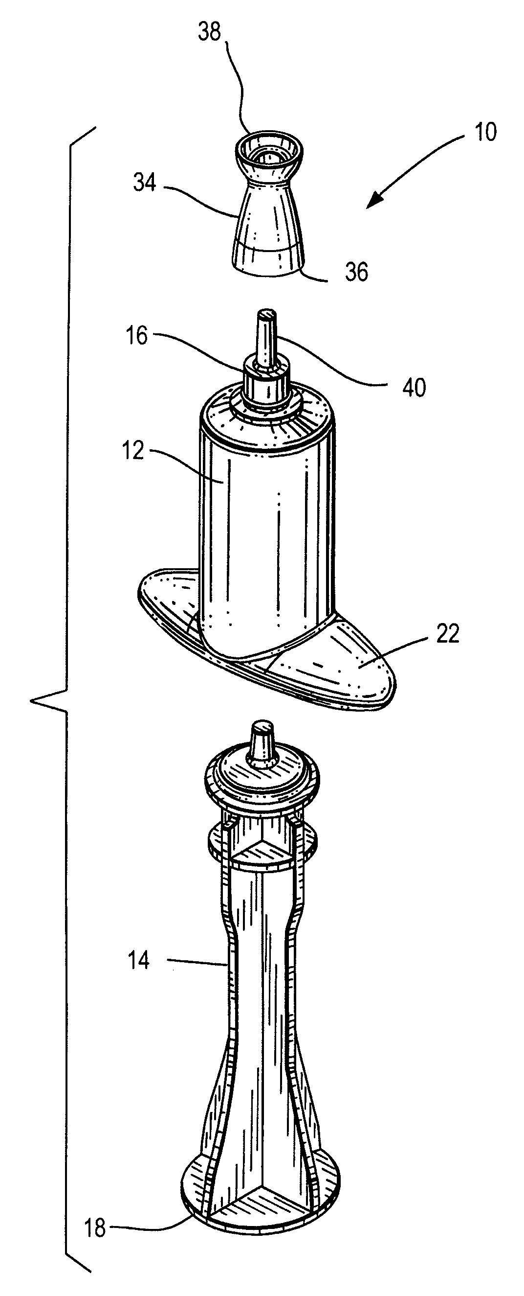
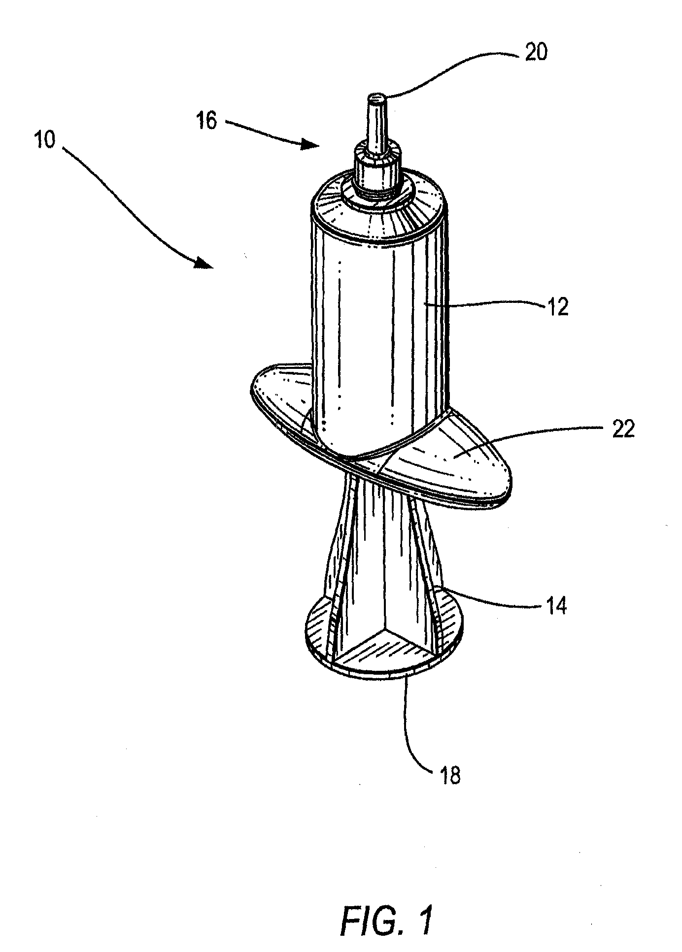
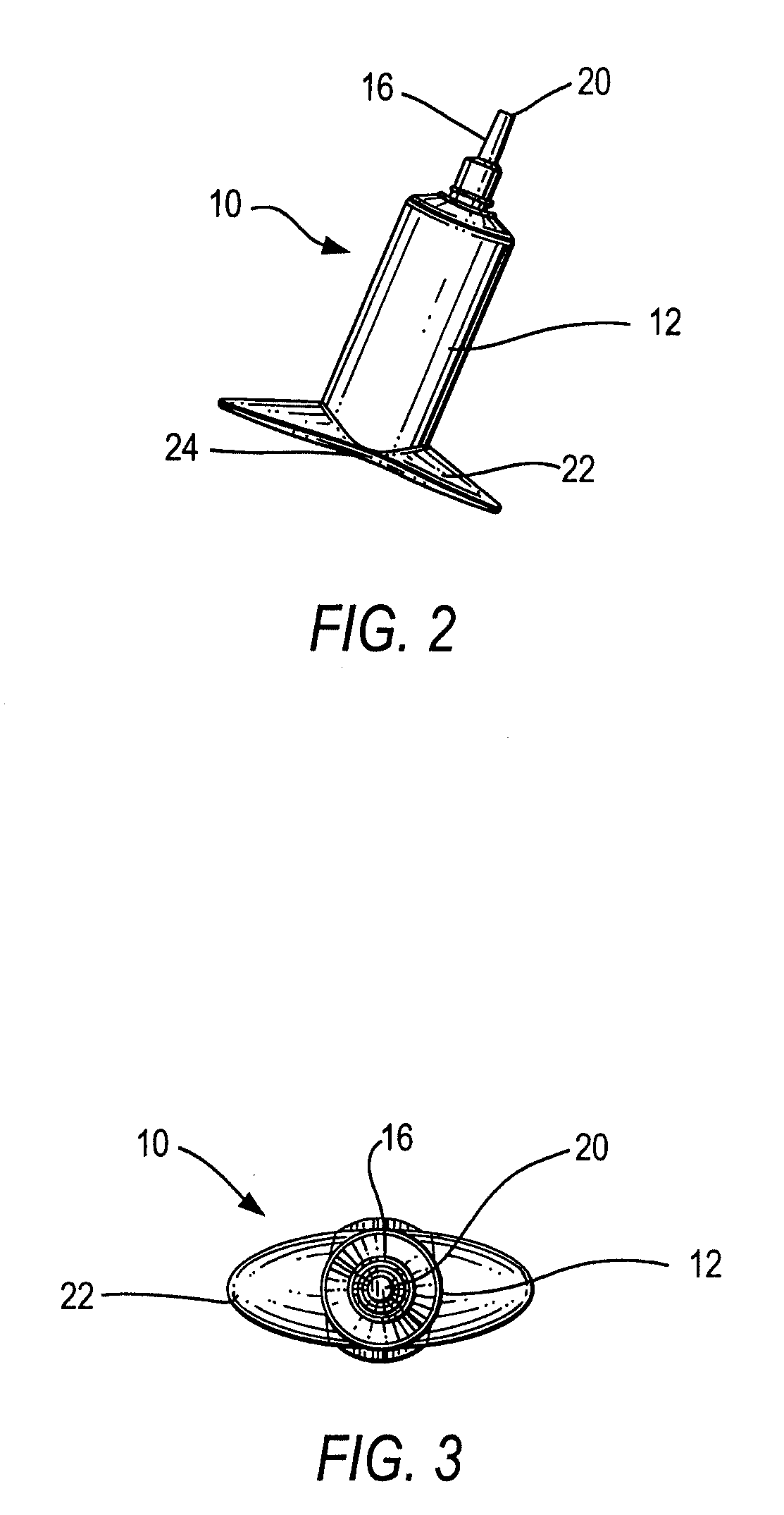
[0059]An embodiment of substance delivery device is depicted in FIG. 1. Substance delivery device 10 may include body 12 and elongated member 14. Elongated member 14 may be positioned within body 12 such that dispensing end 16 of the body and rear end 18 of the elongated member are located opposite ends of the substance delivery device.

[0060]Body 12 may include opening 20 at dispensing end 16 of substance delivery device 10. In some embodiments, multiple openings may be disposed at the end of the substance delivery device. Alternately, some embodiments may include one or more openings proximate dispensing end 16. Openings may be utilized for dispensing substances including but not limited to medicines. In ...


PUM


Abstract

A substance delivery system may include a substance delivery device, a cap, and a removal device. The system may be designed for ease of use. The substance delivery device may include an elongated member adapted to interface with a body. Substance delivery devices may be designed allowing for a predetermined separation distance between the body of the device and end of an elongated member used to drive substance from the device.

Description

INCORPORATION BY REFERENCE[0001]This application claims benefit of New Zealand provisional patent application Serial No. 562037 filed Sep. 27, 2007.[0002]All documents cited or referenced herein (“herein cited documents”), and all documents cited or referenced in herein cited documents, together with any manufacturer's instructions, descriptions, product specifications, and product sheets for any products mentioned herein or in any document incorporated by reference herein, are hereby incorporated herein by reference, and may be employed in the practice of the invention.[0003]In addition, commonly assigned design patent applications of ROBERT WILLIAM LACHLAN HOLMES previously filed as “SYRINGE CAP” (U.S. Application No. 29 / 305,650) and “SYRINGE CAP” (U.S. Application No. 29 / 305,651) are hereby incorporated by reference.FIELD OF THE INVENTION[0004]This invention relates to substance delivery devices and / or caps, particularly but not necessarily solely for use in veterinary applicatio...

Claims


Application Information

Patent Timeline
IPC IPC(8): A61M5/32A61M5/315
CPCA61D1/02A61D7/00A61M5/178A61M5/3137A61M2209/088A61M39/20A61M2005/3104A61M2005/3215A61M5/3204
Inventor SMITH, ROBERTHOLMES, ROBERT WILLIAM LACHLAN
Owner MERIAL LTD
Learn More