
Display device

a display device and display screen technology, applied in the field of display devices, can solve problems such as the demand for flat panel displays (fpds), and achieve the effect of preventing a dark area

Inactive Publication Date: 2009-07-09
SAMSUNG ELECTRONICS CO LTD
View PDF2 Cites 107 Cited by
  • Summary
  • Abstract
  • Description
  • Claims
  • Application Information

AI Technical Summary

Benefits of technology

The present invention provides a display device that can securely receive a display panel and an optical sheet without creating dark areas on the display panel due to an intermediate frame. The device includes a guide member with sidewalls and flanges that hold the display panel and optical sheet in place. The flanges have a top surface that contacts the display panel and a bottom surface that contacts the optical sheet, with a recess forming a space between the top and bottom surfaces. The invention also includes a display panel, guide member, and optical sheet in various embodiments with different features and gaps between the flanges.

Problems solved by technology

In particular, since conventional cathode ray tubes (CRTs) have failed to fully satisfy these market needs, the demand for flat panel displays (FPDs), such as plasma display panels (PDPs), plasma address liquid crystal display panels (PALCs), liquid crystal displays (LCDs), and organic light emitting diodes (OLEDs), is increasing.

Method used


Image

  • Display device
  • Display device
  • Display device

Examples


Embodiment Construction

[0025]Embodiments of the present invention and methods of accomplishing the same may be understood more readily by reference to the following detailed description of exemplary embodiments and the accompanying drawings. The present invention may, however, be embodied in many different forms and should not be construed as being limited to the embodiments set forth herein. Like reference numerals may refer to like elements throughout the specification.

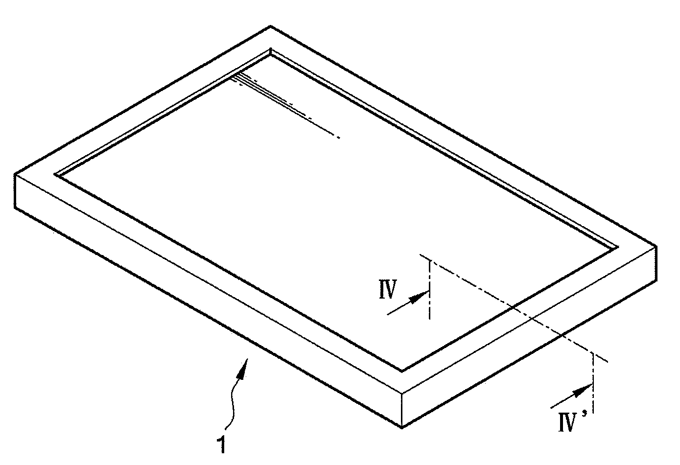
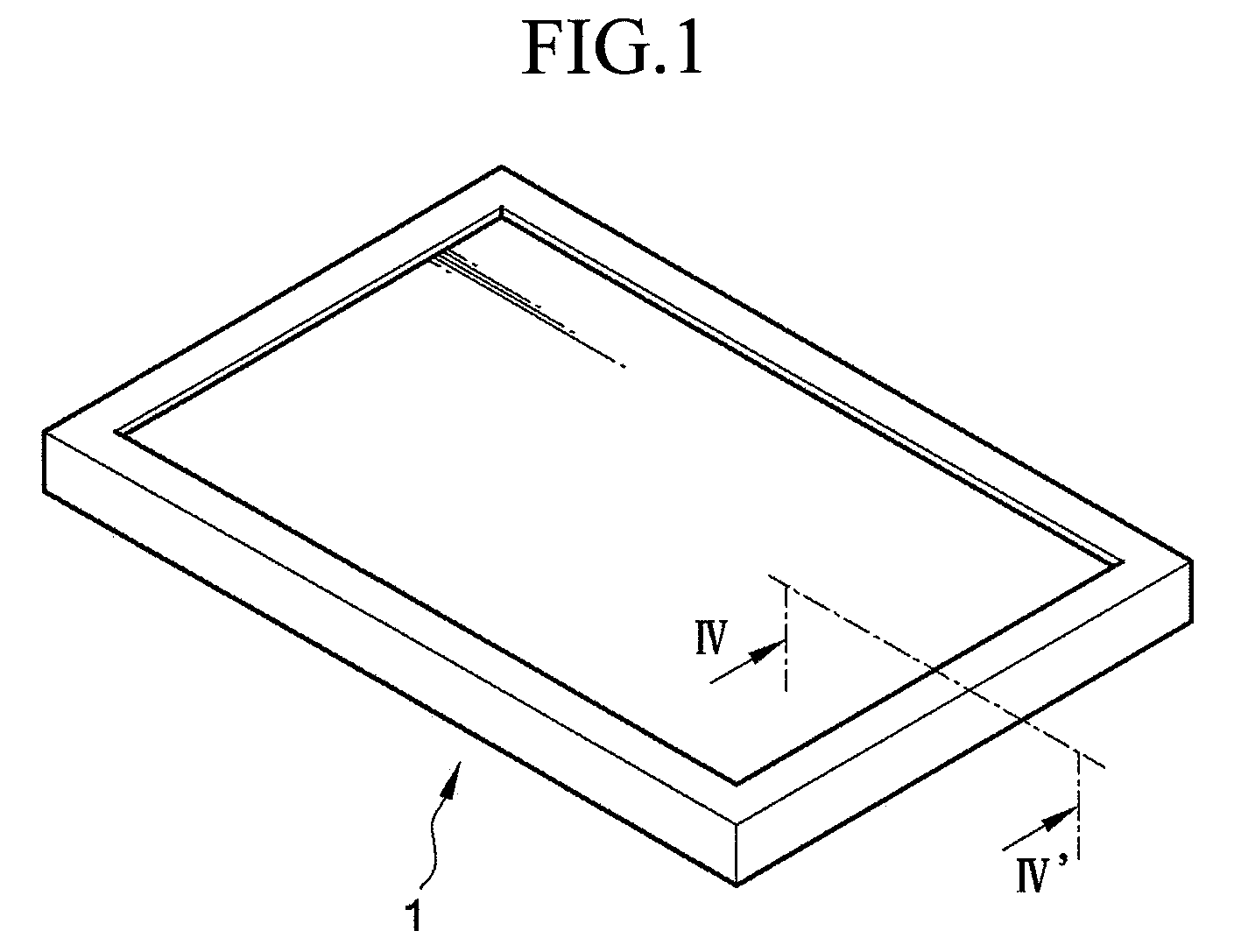
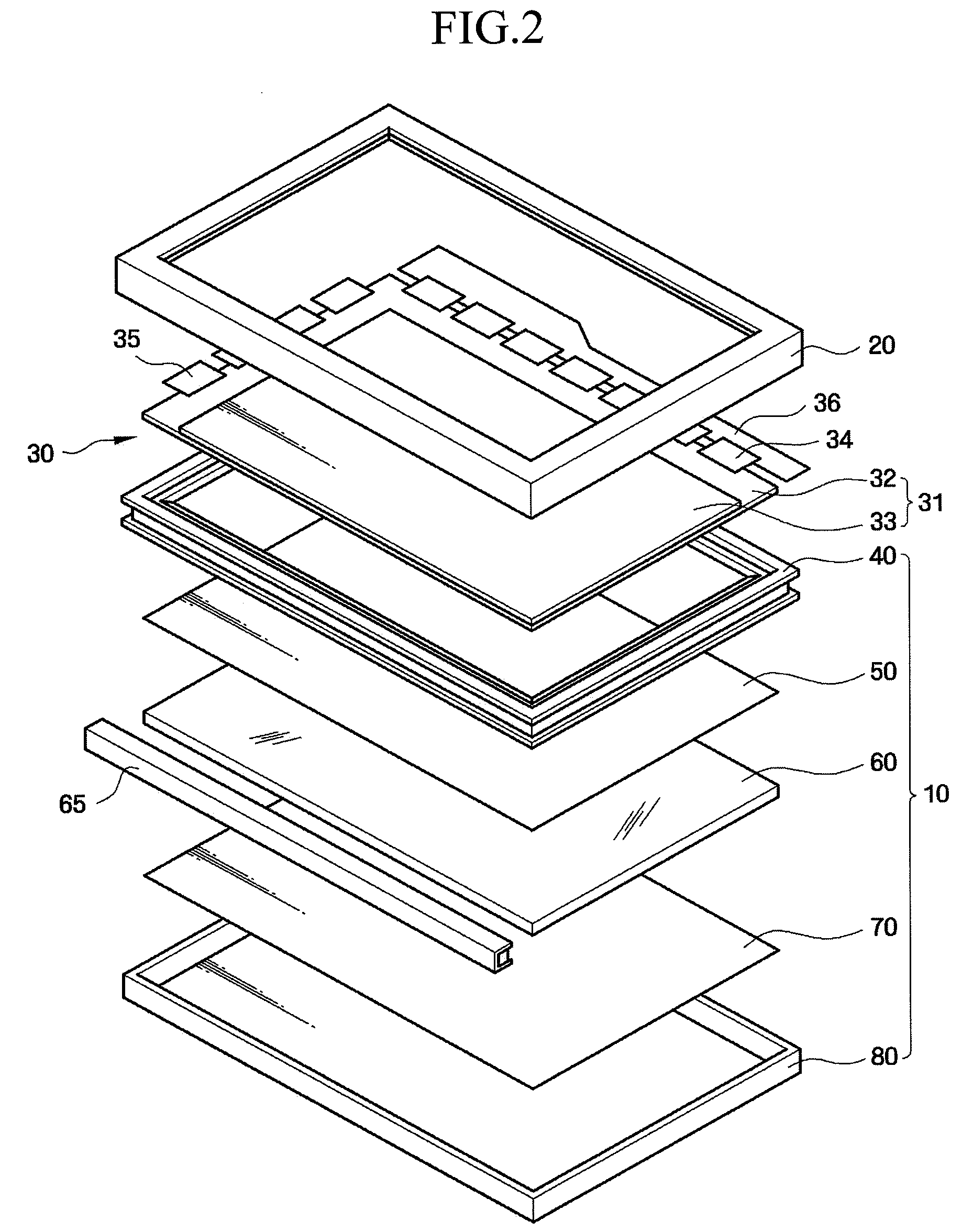
[0026]A liquid crystal display (LCD) according to an exemplary embodiment of the present invention will be described with reference to FIGS. 1 through 4B. FIG. 1 is a perspective view of an LCD 1 according to an exemplary embodiment of the present invention. FIG. 2 is an exploded perspective view of the LCD 1 of FIG. 1. FIG. 3 is a partial perspective view of an intermediate frame 40 included in the LCD 1 of FIG. 1. FIG. 4A is a cross-sectional view of the LCD 1 taken along a line IV-IV′ of FIG. 1. FIG. 4B is an enlarged view of a region ...


PUM


Abstract

A display device which can securely receive a display panel and an optical sheet therein and prevent a dark area from being formed on the display panel due to an intermediate frame. The display device includes a display panel displaying images, a guide member including a plurality of sidewalls and a flange which extends from an inner surface of each sidewall and on which the display panel is placed, and an optical sheet disposed under the flange, wherein the flange includes a top surface, which contacts the display panel, and a bottom surface which contacts the optical sheet, and the bottom surface of the flange extends further from the inner surface of each sidewall than the top surface of the flange.

Description

CROSS-REFERENCE TO RELATED APPLICATION[0001]This application claims priority from Korean Patent Application No. 10-2008-0000802 filed on Jan. 3, 2008 in the Korean Intellectual Property Office, the disclosure of which is incorporated herein by reference in its entirety.BACKGROUND OF THE INVENTION[0002]1. Technical Field[0003]The present invention relates to a display device, and more particularly, to a display device which can securely receive a display panel and an optical sheet therein and prevent a dark area from being formed on the display panel due to an intermediate frame.[0004]2. Discussion of the Related Art[0005]As modern society becomes more dependent on sophisticated information and communication technology, the market needs for larger and thinner displays are growing. In particular, since conventional cathode ray tubes (CRTs) have failed to fully satisfy these market needs, the demand for flat panel displays (FPDs), such as plasma display panels (PDPs), plasma address li...

Claims


Application Information

Patent Timeline
Patent Type & Authority Applications(United States)
IPC IPC(8): G06F1/16H05K7/14
CPCH05K5/0017G02F1/1335
Inventor PARK, SUNG-JAE
Owner SAMSUNG ELECTRONICS CO LTD
Learn More