Dental Handpiece

a handpiece and handpiece technology, applied in the field of dental handpieces, can solve the problems of difficult manipulation of drill bushings, limited use, and removal of drill bushings, and achieve the effects of convenient assembly, accurate control of the position of tools, and convenient cleaning of handpieces

Inactive Publication Date: 2009-07-09
MATERIALISE DENTAL NV
View PDF13 Cites 15 Cited by
  • Summary
  • Abstract
  • Description
  • Claims
  • Application Information

AI Technical Summary

Benefits of technology

[0007]A first aspect of the present invention provides a dental handpiece comprising: a housing; a tool retaining mechanism for retaining a rotary dental tool, the rotary dental tool rotating about a first axis, the mechanism retaining the tool such that the tool extends from the housing along a first axis; and a tubular guide member mounted coaxially with the first axis, the guide member having a tubular part for locating in a bore hole of a template for guiding the working path of the handpiece during use and a flange which extends perpendicularly with respect to the first axis for limiting the depth of the rotary dental tool within the bore hole.
[0008]The provision of a tubular guide member on the dental handpiece has an advantage of allowing accurate control of the position of a tool, as the tool is inserted into a surgical template. As the guide member is mounted to the handpiece, there is no need to remove bushings from a surgical template after drilling operations using the handpiece.
[0009]The handpiece may also include a drive for rotating the retained tool about the first axis. The drive may be a motorised drive such as a pneumatic, hydraulic or electrical drive or components for a manual drive.
[0010]A further aspect of the present invention is that the housing has an inlet through which a tool can be inserted and the handpiece comprises a mechanism for retaining the guide member which is positioned at the inlet. The guide member can be attached to, or attachable to, a mounting part which is mountable around the housing. These features can provide the advantage that assembly of the various parts for mounting the tool are located close to each other and are therefore easy to assemble.
[0011]Preferably, the guide member is positionable at a varying distance from the mounting part. This has the advantage that the tool which is mountable on the handpiece can be adjusted in its position.
[0012]Preferably, the guide member is removably mountable to the handpiece. This provides the advantage that a variety of guide members may be provided and also cleaning of the handpiece is made easier. For example, a set of guide members can be provided which differ in the dimensions of at least one of: flange depth in the direction along the first axis and radius in a direction perpendicular to the first axis. This allows a user to quickly select, and fit, a guide member which has dimensions matched to the particular bore hole diameter and depth of an implant site.

Problems solved by technology

One of the disadvantages of this method relates to the removal of the drill bushings.
Due to limited space in the mouth of the patient, manipulating the drill bushings is difficult.
While the aforementioned tools can be used in combination with a handpiece, their use is limited by the extent that they are compatible with existing implant systems.
One of the disadvantages of the above methods is that dedicated components are required per implant brand and implant line (internal or external connection).
The need for an extensive set of tools and accessories of bespoke sizes makes the solution expensive and inflexible.

Method used


Image

  • Dental Handpiece
  • Dental Handpiece
  • Dental Handpiece

Examples


Embodiment Construction

[0043]The present invention will be described with respect to particular embodiments and with reference to certain drawings but the invention is not limited thereto but only by the claims. The drawings described are only schematic and are non-limiting. In the drawings, the size of some of the elements may be exaggerated and not drawn on scale for illustrative purposes. Where the term “comprising” is used in the present description and claims, it does not exclude other elements or steps. Furthermore, the terms first, second, third and the like in the description and in the claims, are used for distinguishing between similar elements and not necessarily for describing a sequential or chronological order. It is to be understood that the terms so used are interchangeable under appropriate circumstances and that the embodiments of the invention described herein are capable of operation in other sequences than described or illustrated herein.

[0044]Before describing the drilling assembly i...


PUM


Abstract

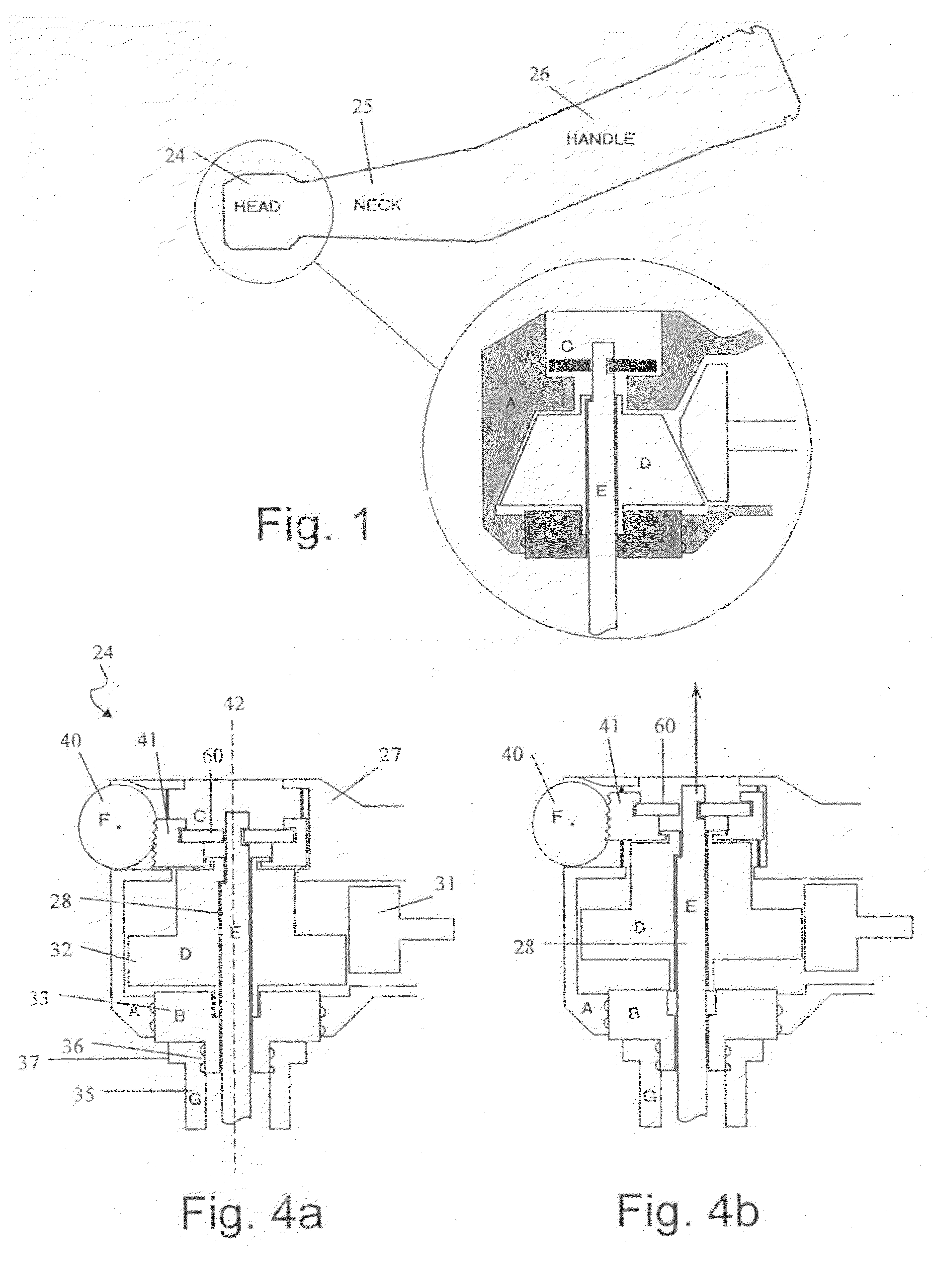
A dental handpiece comprises a housing (27) and a tool retaining mechanism (60) for retaining a rotary dental tool (28). The rotary dental tool rotates about a first axis (42) and the mechanism retaining the tool such that the tool extends from the housing along the first axis. A tubular guide member (35) is mounted coaxially with the first axis and has a tubular part for locating in a bore hole of a template. This serves to guide the working path of the handpiece during use. A flange (37) on the guide member extends perpendicularly with respect to the first axis and limits the depth of the rotary dental tool within the bore hole. The dental handpiece may also comprise an adjustment mechanism which adjusts the position of the tool retaining mechanism within the housing, in the direction of the first axis, to vary the length of tool which projects from the housing.

Description

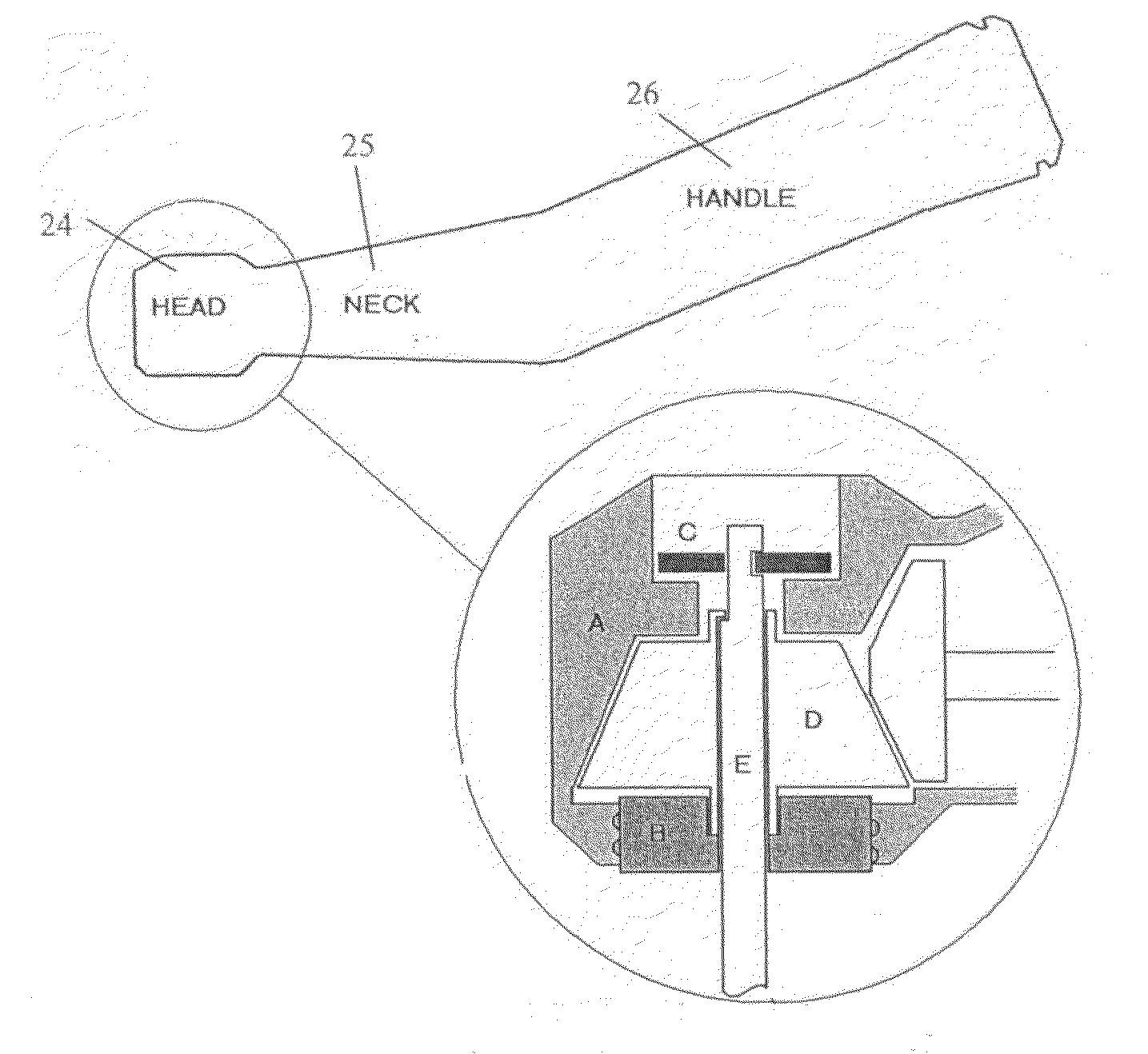
FIELD OF THE INVENTION[0001]This invention relates to a dental handpiece and a process of fitting dental implants using the handpiece.BACKGROUND TO THE INVENTION[0002]In dental treatment drive apparatuses for rotary tools, known as handpieces, are well known. Dental handpieces come in several shapes and most commonly are either straight or have a swan neck. FIG. 1 shows a typical swan-necked dental handpiece, which comprises a handle 26, a neck 25 and a head 24 in which a rotary tool (e.g. drill, bur, implant driver) is fixed. The handpiece is typically driven by a drive shaft or belt, which extends between the head of the handpiece and a remotely located drive motor. The drive shaft transmits the rotational movement of the motor to the handpiece. Handpieces can alternatively be driven by electric or pneumatic drive motors. Handpieces are used to drive tools during various dentistry operations, such as filling cavities, cleaning and the fitting of dental implants.[0003]A known denti...

Claims


Application Information

Patent Timeline
Patent Type & Authority Applications(United States)
IPC IPC(8): A61C19/00A61C3/00A61C3/02
CPCA61B2019/306A61C1/084A61C1/144A61C1/141A61C1/12A61B2090/036A61C5/44A61C1/142
Inventor ESPOSTI, ALESSIOVAN LIERDE, CARL
Owner MATERIALISE DENTAL NV
Why Eureka
Try Eureka