
Closure for a movable roof

Inactive Publication Date: 2009-07-16
MAGNA CAR TOP SYST GMBH
View PDF17 Cites 4 Cited by
  • Summary
  • Abstract
  • Description
  • Claims
  • Application Information

AI Technical Summary

Benefits of technology

[0008]An object of the present invention includes a closure assembly for a movable roof of a vehicle in which the closure assembly is implemented relatively easily and functions well with relatively favorable space requirements.
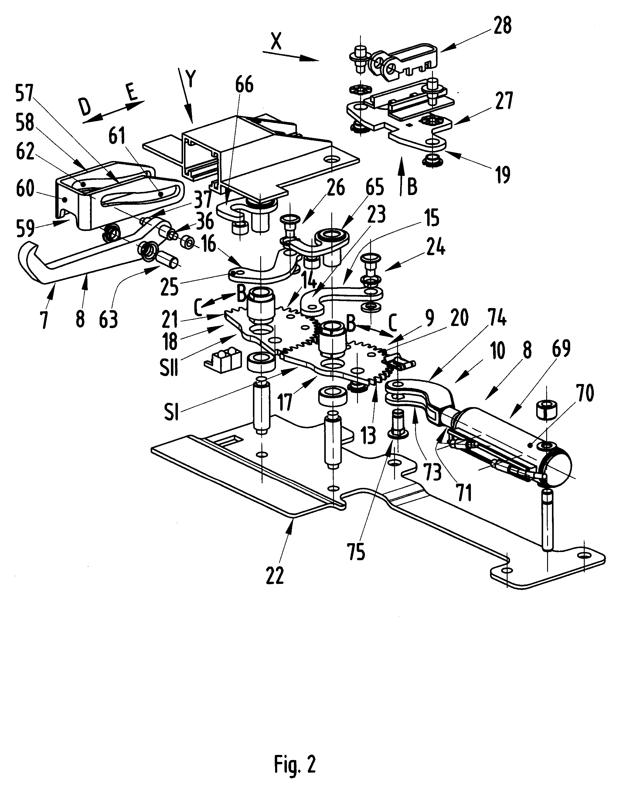
[0011]Advantages achieved by a closure assembly in accordance with embodiments of the present invention are that, due to the ideal design of the gearwheels (“gears”) and levers, which allow a compact structure and have low space requirements and which may be accommodated on the movable roof in an ideal manner, the closure assembly which is to act between the roof and a vehicle (e.g., windshield) frame functions well and is easily implemented. Because of their identical design, the gears and levers represent ideal components which have superior function and a long service life. This is also assisted by the rotational axes of the gears and the articulated axes of the levers. Furthermore, the actuator may include a base plate having a bearing support bracket and guide tracks and the closure assembly may further include a receiving element and a slide support which are components which may be manufactured and installed with a reasonable level of effort. Force absorption devices counteract uncontrolled release of the closure assembly from its locked position, for example under the effect of frontal or rear impact damage sustained by the vehicle. Lastly, the closure assembly may thus be actuated in a targeted and functionally correct manner when it is provided with a corresponding drive unit.

Problems solved by technology

Force absorption devices counteract uncontrolled release of the closure assembly from its locked position, for example under the effect of frontal or rear impact damage sustained by the vehicle.

Method used


Image

  • Closure for a movable roof
  • Closure for a movable roof
  • Closure for a movable roof

Examples


Embodiment Construction

)

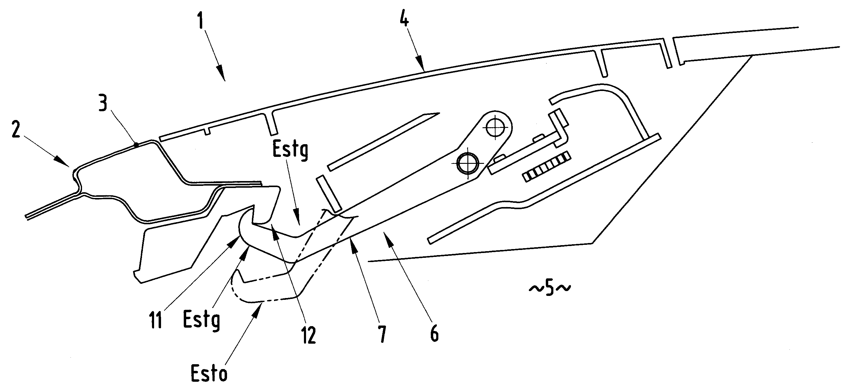
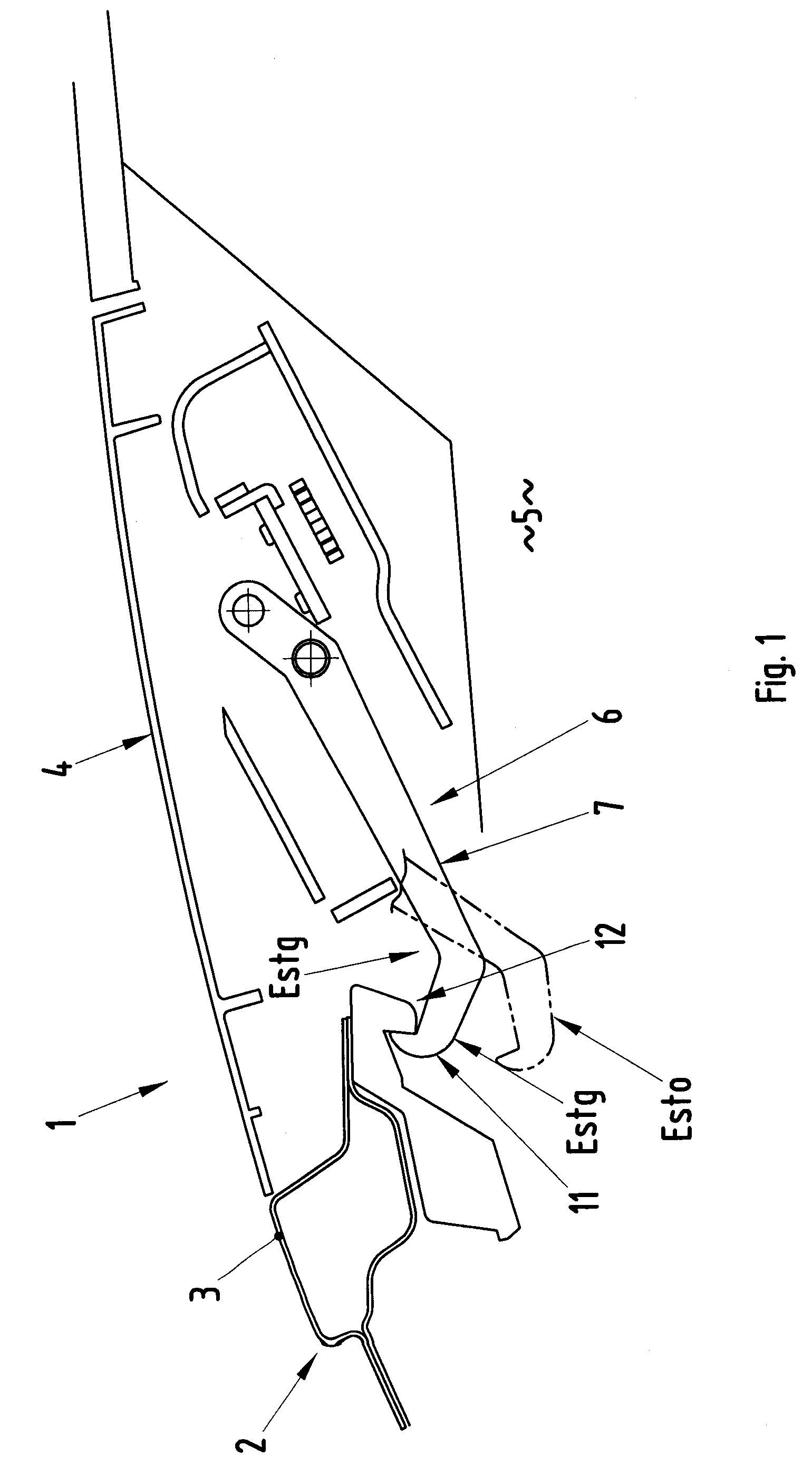
[0020]Referring now to the FIGURES, a closure assembly for a movable roof 4 of a vehicle 1 in accordance with an embodiment of the present invention is shown. Vehicle 1 is a convertible and includes a vehicle body 2 with a front windshield frame 3. Roof 4 is movably connected to vehicle body 2 to move between a closed position in which roof 4 spans passenger compartment 5 of vehicle 1 with a front portion of roof 4 adjoining windshield frame 3 and an opened position in which roof 4 is moved rearwardly to expose passenger compartment 5.

[0021]The closure assembly is connected to roof 4 and functions to lock roof 4 in place to vehicle 1 when roof 4 is in the closed roof position. The closure assembly further functions to unlock roof 4 from the closed roof position when roof 4 is to move from the closed roof position to the opened roof position.

[0022]The closure assembly generally includes a closure 6, a drive unit 10, an actuator 19, a receiving element 52, and a support element 59 (F...


PUM


Abstract

A closure assembly for a vehicle includes a hook movable between locked and unlocked positions. An actuator is connected to the hook and is linearly movable to move the hook between the locked and unlocked positions. First and second rotatable gears are engaged with one another such that either gear rotates as the other gear rotates. First and second levers are respectively connected between the gears and the actuator. The levers move as the gears rotate in response to the first gear rotating in a first rotary direction and thereby cause the actuator to move linearly in a first direction to thereby move the hook to the locked position. The levers move as the gears rotate in response to the first gear rotating in a second rotary direction and thereby cause the actuator to move linearly in a second direction to thereby move the hook to the unlocked position.

Description

CROSS-REFERENCE TO RELATED APPLICATIONS[0001]This application claims foreign priority benefits under 35 U.S.C. § 119(a)-(d) to DE 10 2008 003 880.6, filed Jan. 10, 2008, which is hereby incorporated by reference in its entirety.BACKGROUND OF THE INVENTION[0002]1. Field of the Invention[0003]The present invention relates to closure assemblies for movable roofs of vehicles.[0004]2. Background Art[0005]DE 10 2004 046 098 A1 (corresponding to U.S. Pat. No. 7,407,201) describes a closure assembly for a movable roof of a vehicle. The closure assembly acts between the roof and the vehicle windshield frame and includes a slide linkage-controlled locking hook. The locking hook may move between closed and opened positions via a guide device. The locking hook cooperates with a hook guide in mechanical linkage with a motorized gearing assembly.[0006]DE 100 00 002 A1 (corresponding to U.S. Pat. No. 6,520,560) describes a locking assembly for a movable roof of a vehicle. The locking assembly incl...

Claims


Application Information

Patent Timeline
IPC IPC(8): B60J7/185
CPCB60J7/1851
Inventor SCHUMACHER, THORSTENKLEMM, HOLGER
Owner MAGNA CAR TOP SYST GMBH
Learn More