Virtual moving screen for rendering three dimensional image

a three-dimensional image and virtual moving screen technology, applied in the field of three-dimensional imaging, can solve the problems of low resolution, translucent image representation, and insufficient technology to achieve the effect of achieving the effect of achieving the effect of achieving the effect of achieving the effect of achieving the effect of achieving the effect of achieving the effect of achieving the effect of achieving the effect of achieving the effect of achieving the effect of achieving the effect of achieving the effect of achieving the effect o

Inactive Publication Date: 2009-07-16
THE BOARD OF RGT UNIV OF OKLAHOMA
View PDF22 Cites 57 Cited by
  • Summary
  • Abstract
  • Description
  • Claims
  • Application Information

AI Technical Summary

Benefits of technology

[0028]FIG. 12 illustrates the effect of the translation motion of FIG. 11

Problems solved by technology

In practice, these technologies have not fully achieved their objectives and posses

Method used


Image

  • Virtual moving screen for rendering three dimensional image
  • Virtual moving screen for rendering three dimensional image
  • Virtual moving screen for rendering three dimensional image

Examples


Embodiment Construction

[0032]Present embodiments of the invention are shown in the above-identified figures and described in detail below. In describing the embodiments, like or identical reference numerals are used to identify common or similar elements. The Figures are not necessarily to scale and certain features in certain views of the Figures may be shown exaggerated in scale or in schematic in the interest of clarity and conciseness.

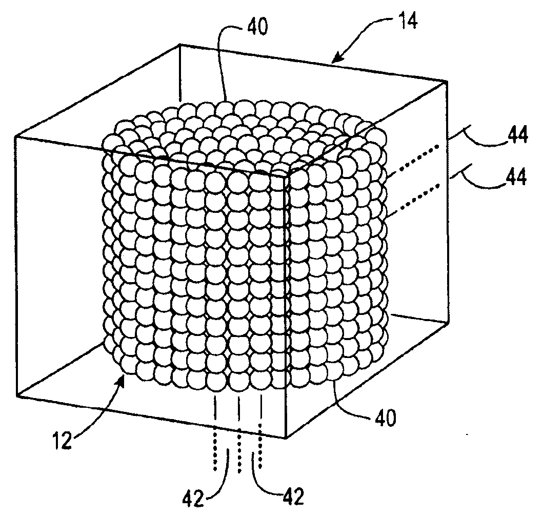
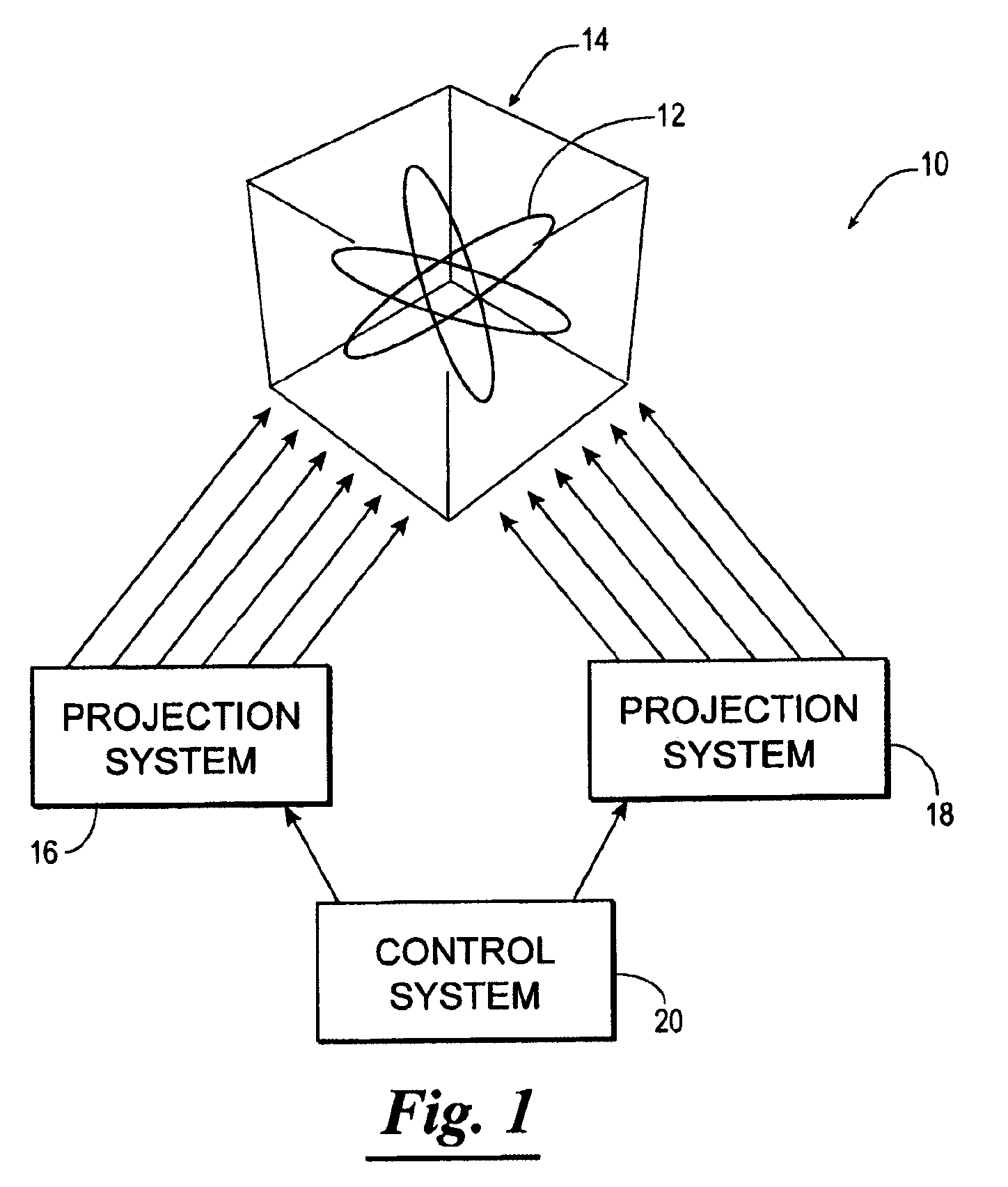
[0033]Referring now to the drawings, and in particular to FIG. 1, shown therein and designated by reference numeral 10 is a light surface display, constructed in accordance with the present invention, for providing a three-dimensional image 12 within a volumetric display 14. In general, the light surface display 10 includes a plurality of particles, suspended within the volumetric display 14, that when energized by electromagnetic energy, illuminate forming a three-dimensional image 12.

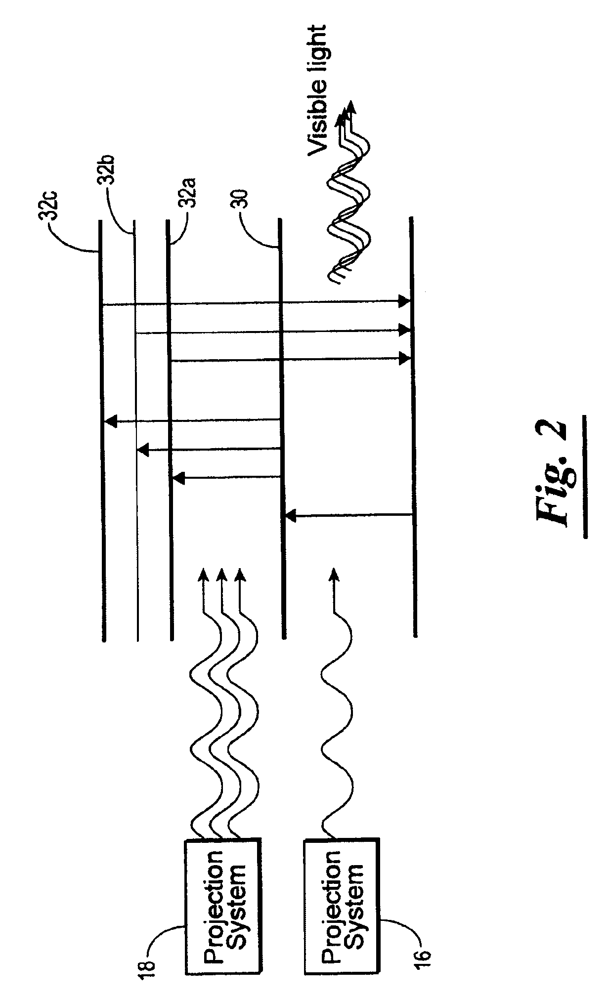
[0034]The light surface display 10 is provided with a first projection system 16 proje...


PUM


Abstract

A method of producing multiple three-dimensional images to create an optical illusion of movement, comprising the steps of: (a) energizing particles suspended within a volumetric display sequentially along the length and width of the volumetric display through projection of electromagnetic energy of one or more wavelengths, the energized particles forming a two-dimensional image; b. intersecting the energized particles through projection of electromagnetic energy of one or more wavelengths along the depth of the volumetric display; c. synchronizing the projection of electromagnetic energy along the length and width of the volumetric display with the projection of electromagnetic energy along the depth of the volumetric display for a pre-determined length of time forming an illuminated three-dimensional image; and d. repeating steps a, b and c for each of the plurality of three-dimensional images using a predetermined scanning sequence to create the optical illusion of movement.

Description

CROSS-REFERENCE TO RELATED APPLICATIONS[0001]The present patent application claims priority to the provisional patent application identified by U.S. Ser. No. 61 / 020,935, the entire content of which is hereby incorporated herein by reference.STATEMENT REGARDING FEDERALLY SPONSORED RESEARCH OR DEVELOPMENT[0002]Not applicable.NAMES OF PARTIES TO A JOINT RESEARCH AGREEMENT[0003]Not applicable.REFERENCE TO A “SEQUENCE LISTING”, A TABLE, OR A COMPUTER PROGRAM LISTING APPENDIX SUBMITTED ON A COMPACT DISC AND AN INCORPORATION BY REFERENCE OF THE MATERIAL ON THE COMPACT DISC[0004]Not applicable.BACKGROUND OF THE INVENTION[0005]Technological advances of the last decade have made scientists and engineers increasingly aware of three dimensional imaging as both viable and realistic. There is now widely acknowledged incentive, both commercially and industrially, for developing a color 3-D display system that can be viewed from unencumbered perspectives. Recent developments using micro-materials a...

Claims


Application Information

Patent Timeline
IPC IPC(8): G09G3/34
CPCH04N13/049G09G3/001H04N13/39
Inventor REFAI, HAKKI H.SLUSS, JR., JAMES J.
Owner THE BOARD OF RGT UNIV OF OKLAHOMA
Why Eureka
Try Eureka