
Low side driver with short to battery protection

Inactive Publication Date: 2009-07-16
VISTEON GLOBAL TECH INC
View PDF4 Cites 2 Cited by
  • Summary
  • Abstract
  • Description
  • Claims
  • Application Information

AI Technical Summary

Benefits of technology

[0007]Accordingly, a driver circuit having a short-circuit protection circuit is provided without requiring software intervention and to protect the first transistor, i.e. driver. Therefore, less electronic components are required and a more cost-efficient driver circuit can be constructed.

Problems solved by technology

Under normal operating conditions, the current through the driver is further limited due to the impedance of the inductive load.
However, it is possible a short-circuit in the node including the driver can occur that causes excessive current flow through the driver.
As a result, the driver can be damaged.
Although a driver can be protected using software intervention and microcontrollers, the resulting driver circuit can be very costly, especially in high current applications.

Method used


Image

  • Low side driver with short to battery protection
  • Low side driver with short to battery protection

Examples


Embodiment Construction

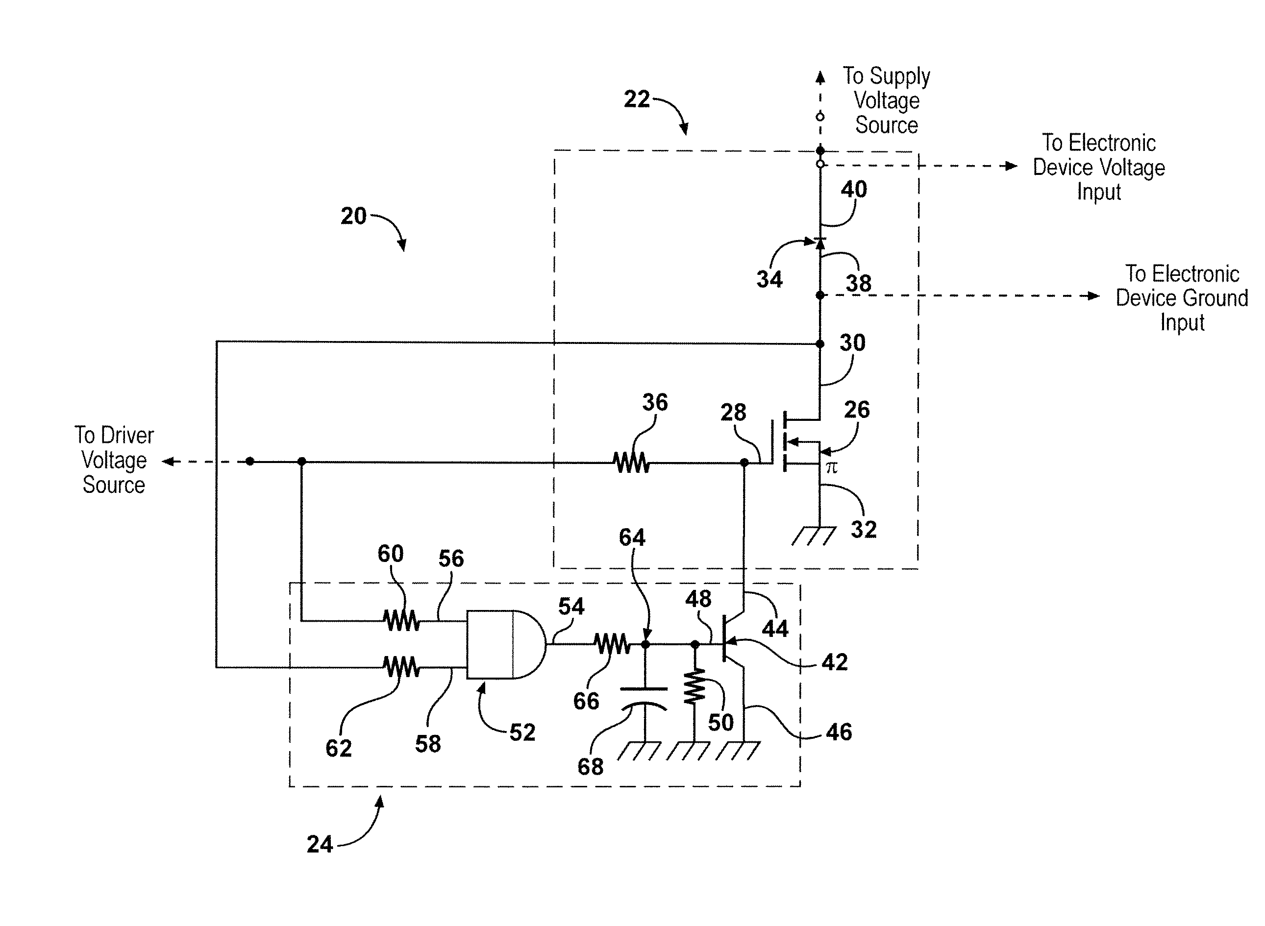
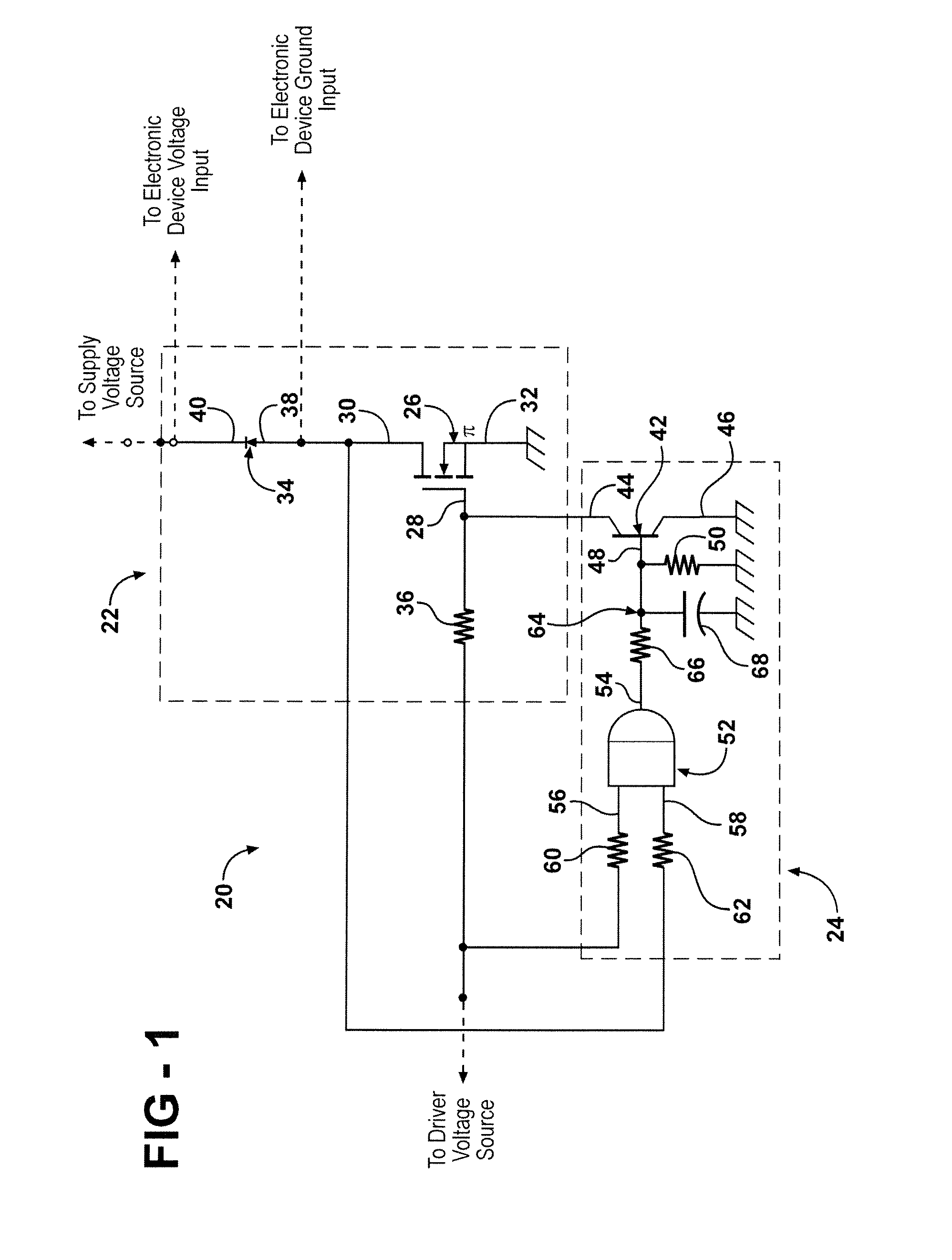
[0010]Referring to the Figures, wherein like numerals indicate corresponding parts throughout the several views, a driver circuit 20 is generally shown for conducting current through an electronic device (not shown) connected to a supply voltage source (not shown). The driver circuit 20 includes a driver module 22 generally indicated and a protection module 24 generally indicated. In general, the driver module 22 is connected to the supply voltage source and the electronic device. When the driver module 22 is connected to a driver voltage source (not shown), the driver module 22 conducts current from the supply voltage source through the electronic device to provide power thereto. The driver source may be any power source that provides power to the driver module, including, but not limited to an alternating current power supply (AC power supply), a direct current power supply (DC power supply), or a pulse width modulation power supply (PWM power supply).

[0011]More specifically, the ...


PUM


Abstract

A driver circuit includes a driver module having a first transistor for receiving a driver voltage signal. In response to the driver voltage signal, the first transistor conducts current through an electronic device. A protection module includes a second transistor in electrical communication with the first transistor for receiving a logic voltage signal and for inhibiting current flow through the first transistor in response to receiving the logic voltage signal. The protection module further includes a digital logic gate having at least one input in electrical communication with the first transistor for detecting a short-circuit voltage signal. At least one output of the digital logic gate is in electrical communication with the second transistor for outputting the logic voltage signal in response to receiving the short-circuit voltage signal.

Description

BACKGROUND OF THE INVENTION[0001]1. Field of the Invention[0002]The present invention relates to electronic circuits, and specifically, to a driver circuit for conducting current through an electronic device connected to a supply voltage source.[0003]2. Description of the Prior Art[0004]Traditional drive circuits provide one or more transistors i.e. drivers for driving current through an inductive load. Typically, additional electronic components are provided to limit the current delivered to the driver. Under normal operating conditions, the current through the driver is further limited due to the impedance of the inductive load. However, it is possible a short-circuit in the node including the driver can occur that causes excessive current flow through the driver. As a result, the driver can be damaged.[0005]Short-circuit protection circuits exist to protect drivers from current damage resulting from short-circuits. Traditional short-circuit protection circuits provide fully prote...

Claims


Application Information

Patent Timeline
IPC IPC(8): H02H9/00G05F3/02
CPCH03K17/0822H03K17/6877H03K17/284
Inventor SHARAA, IMAD
Owner VISTEON GLOBAL TECH INC
Learn More