Switching power supply apparatus and semiconductor device used in the switching power supply apparatus

Inactive Publication Date: 2009-07-16
PANASONIC CORP
View PDF4 Cites 47 Cited by
  • Summary
  • Abstract
  • Description
  • Claims
  • Application Information

AI Technical Summary

Benefits of technology

[0024]The present invention was devised in view of the problems described above, an object thereof being to provide a switching power supply apparatus which is capable of achieving highly accurate overvolt

Problems solved by technology

This overvoltage state of the output DC voltage causes damage to the constituent elements of the switching power supply apparatus and to the load.
However, a switching power supply apparatus having a composition which protects against overvoltage by detecting the overvoltage state of the output DC voltage Vout on the basis of the voltage applied to the VCC terminal involves the following problems.
As described above, a switching power supply apparatus which carries out overvoltage protection by detecting the overvoltage state of the output DC voltage Vout on the basis of the voltage applied to the VCC terminal has problems in that it does not enable overvoltage protection to be carried out with good accuracy.
Furthermore, even during the normal operation when the output DC voltage Vout is stabilized to a prescribed voltage, if the output power has increased due to the effects of the ringing component which occurs in the voltage of the auxiliary winding 31c as described above, then the voltage at the VCC terminal may increase to the voltage at which the overvoltage protection operates, and therefore an overvoltage state of the output DC voltage Vout may

Method used


Image

  • Switching power supply apparatus and semiconductor device used in the switching power supply apparatus
  • Switching power supply apparatus and semiconductor device used in the switching power supply apparatus
  • Switching power supply apparatus and semiconductor device used in the switching power supply apparatus

Examples


first embodiment

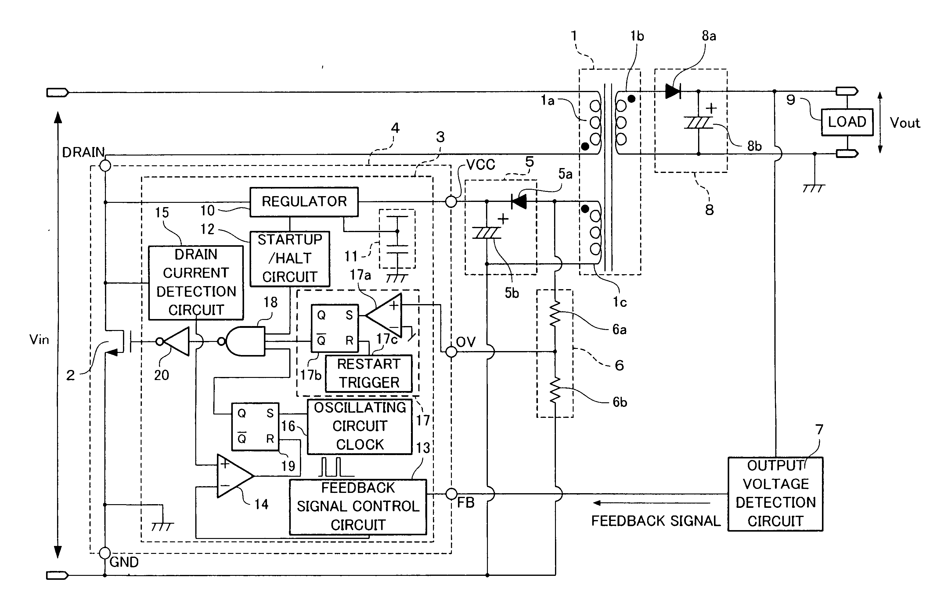
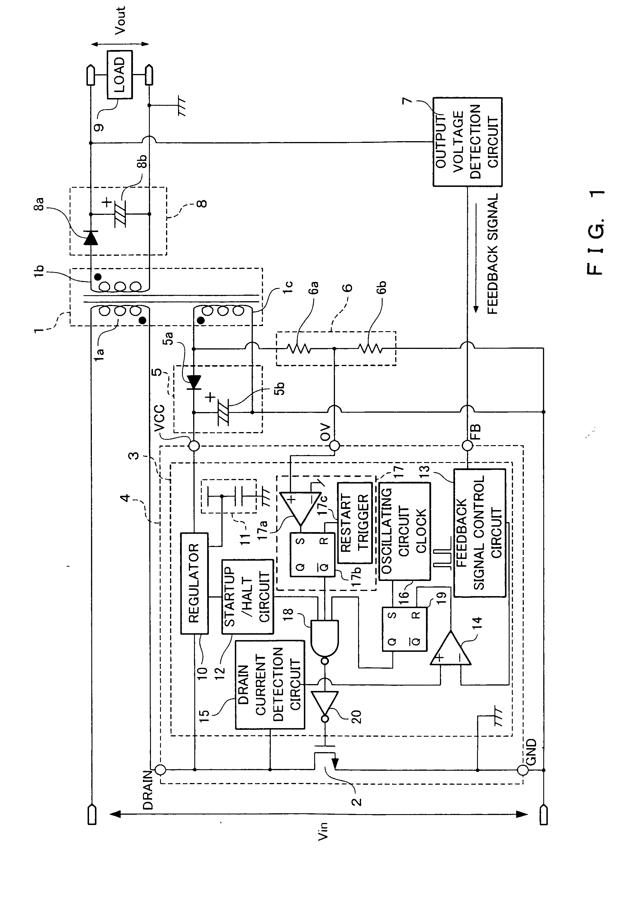
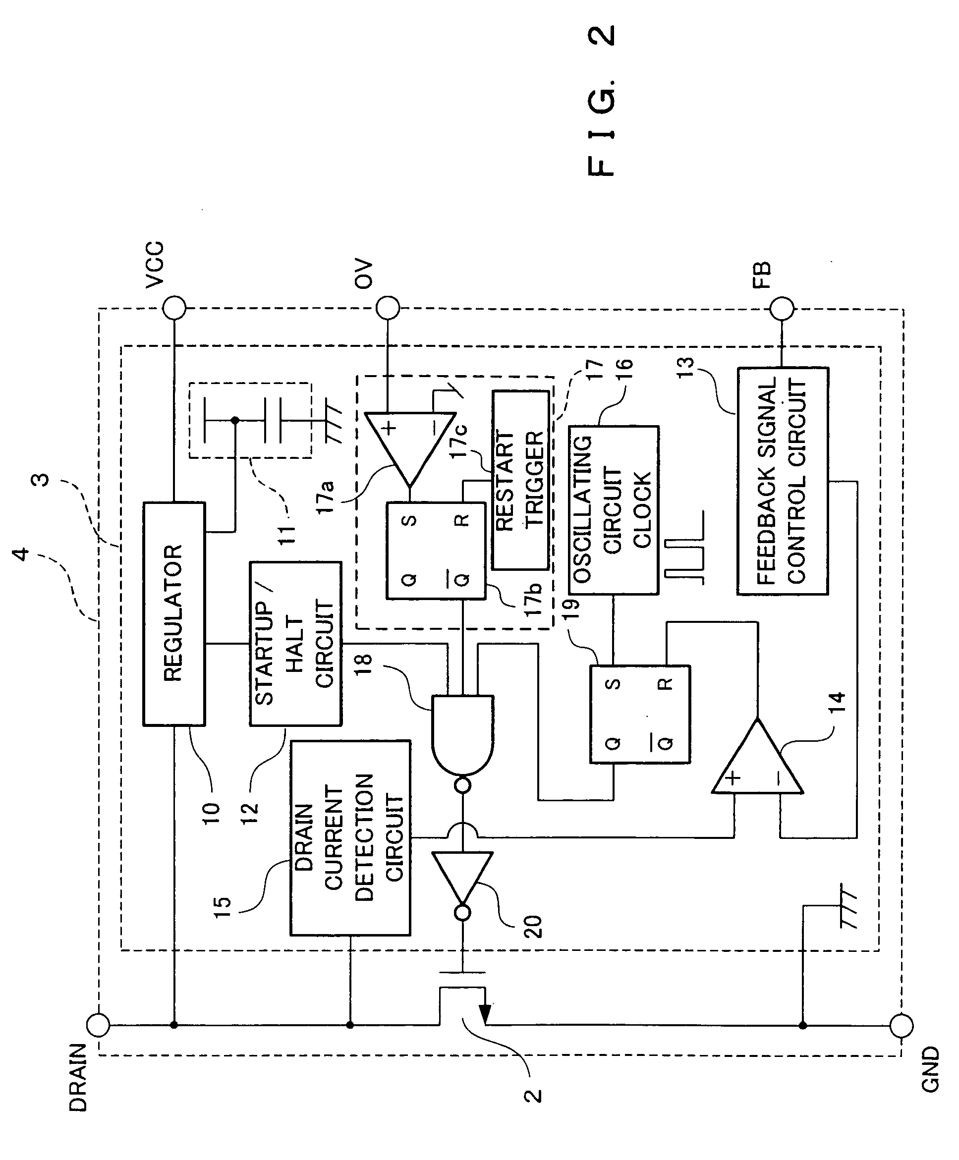
[0052]Below, one example of the composition of a switching power supply apparatus relating to a first embodiment of the present invention and a semiconductor device used in this switching power supply apparatus will be described with reference to the drawings. FIG. 1 is a circuit diagram which shows one example of the composition of the switching power supply apparatus relating to the first embodiment of the present invention, and FIG. 2 is a circuit diagram which shows one example of the composition of the semiconductor device which is used in this switching power supply apparatus. This switching power supply apparatus uses current-mode PWM control as a method for controlling the switching operation of a switching element.

[0053]As shown in FIG. 1, a switching transformer 1 comprises a primary winding 1a, a secondary winding 1b and an auxiliary winding 1c. The primary winding 1a and the secondary winding 1b have opposite polarities, and the switching power supply apparatus is a flyb...

second embodiment

[0104]Next, one example of the composition of a switching power supply apparatus relating to a second embodiment of the present invention and a semiconductor device used in this switching power supply apparatus will be described with reference to the drawings. Only those points which differ from the switching power supply apparatus and the semiconductor device relating to the first embodiment described above will be explained.

[0105]FIG. 7 is a circuit diagram showing one example of the composition of the semiconductor device which is used in the switching power supply apparatus relating to the second embodiment of the present invention. Members which correspond to members that were described in the first embodiment are labeled with the same reference numerals.

[0106]This switching power supply apparatus differs from the switching power supply apparatus relating to the first embodiment described above in respect of the composition of a control circuit 3 which is incorporated in a semi...

third embodiment

[0116]Next, one example of the composition of a switching power supply apparatus relating to a third embodiment of the present invention and a semiconductor device used in this switching power supply apparatus will be described with reference to the drawings. Only those points which differ from the switching power supply apparatus and the semiconductor device relating to the first and second embodiments described above will be explained.

[0117]FIG. 9 is a circuit diagram showing one example of the composition of the semiconductor device which is used in the switching power supply apparatus relating to the third embodiment of the present invention. Members which correspond to members that were described in the first and second embodiments are labeled with the same reference numerals.

[0118]This switching power supply apparatus differs from the switching power supply apparatus relating to the first and second embodiments described above in respect of the composition of the control circu...


PUM


Abstract

A switching power supply apparatus having a highly accurate overvoltage protection function which is free of erroneous operation is provided. A regulating circuit connected to an auxiliary winding generates an AC voltage proportional to a voltage component in which the ringing component has been removed from the AC voltage induced in the auxiliary winding by the switching operation of a switching element. If the peak value of the AC voltage generated by the regulating circuit is equal to or greater than a prescribed value, an overvoltage detection circuit controls the switching operation of the switching element so as to reduce the output DC voltage.

Description

BACKGROUND OF THE INVENTION[0001]1. Field of the Invention[0002]The present invention relates to a switching power supply apparatus which has an overvoltage protection function, and to a semiconductor device which is used in such a switching power supply apparatus.[0003]2. Description of the Related Art[0004]A switching power supply apparatus is used in order to supply a stable DC voltage to a load. However, due to various reasons, the output DC voltage supplied from a switching power supply apparatus to a load may assume an overvoltage state which is higher than the prescribed voltage. This overvoltage state of the output DC voltage causes damage to the constituent elements of the switching power supply apparatus and to the load. In order to prevent damage of this kind, a switching power supply apparatus has been proposed which has an overvoltage protection function that reduces the output DC voltage in cases where the output DC voltage has assumed an overvoltage state.[0005]FIG. 1...

Claims


Application Information

Patent Timeline
IPC IPC(8): H02M3/335
CPCH02M3/33523
Inventor KAWABE, KEITAYAMASHITA, TETSUJI
Owner PANASONIC CORP
Why Eureka
Try Eureka