Headphone amplifier circuit

Inactive Publication Date: 2009-07-16
LAPIS SEMICON CO LTD
View PDF4 Cites 5 Cited by
  • Summary
  • Abstract
  • Description
  • Claims
  • Application Information

AI Technical Summary

Benefits of technology

[0015]As described above, the present invention has an excellent advantageous effect that the influence of parasitic resistance d

Problems solved by technology

A problem however arises in that when the value of Rc is large, the influence of an input signal of another channel on

Method used


Image

  • Headphone amplifier circuit
  • Headphone amplifier circuit
  • Headphone amplifier circuit

Examples


Embodiment Construction

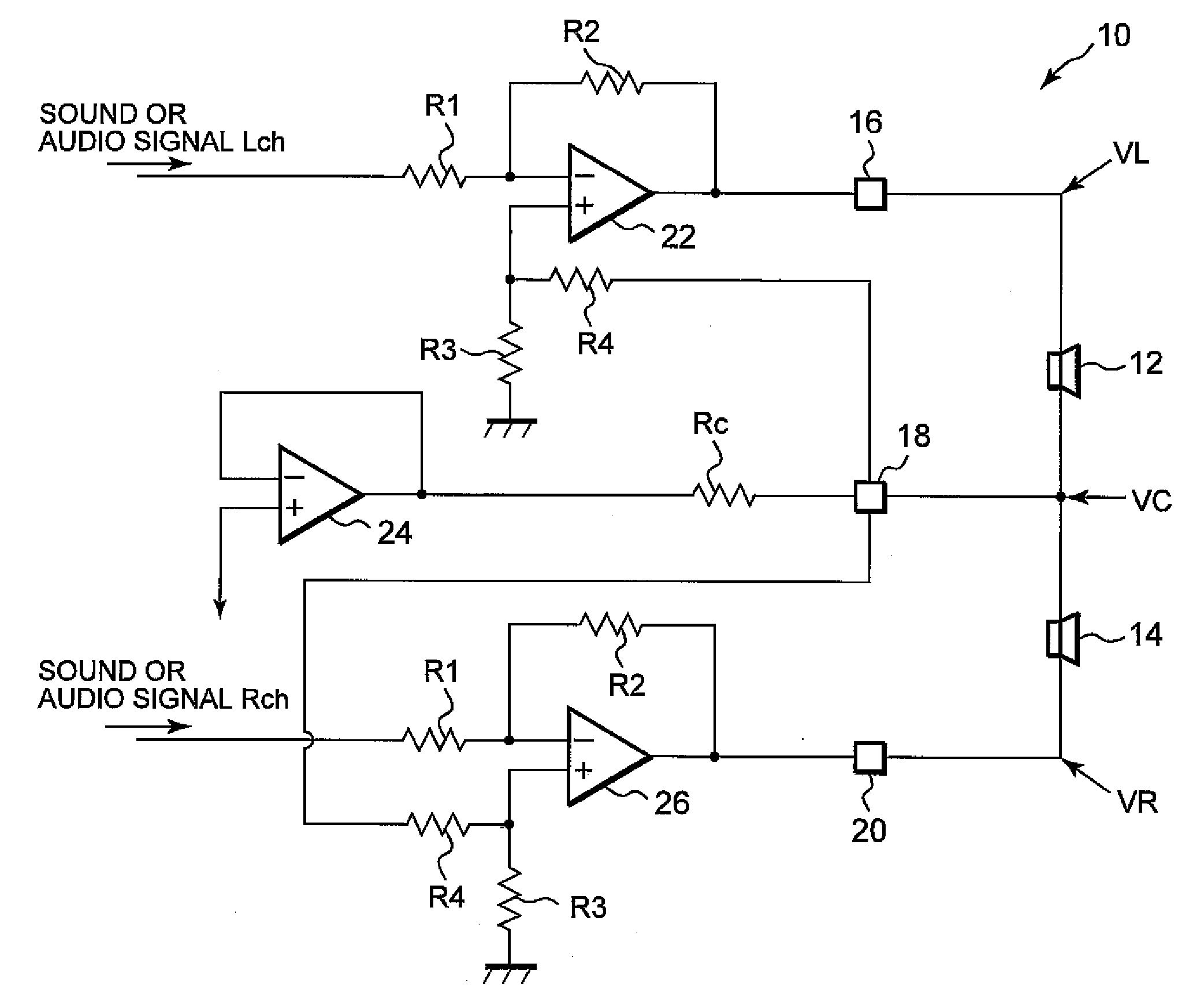
[0019]A preferred embodiment of the present invention will hereinafter be described in detail with reference to the accompanying drawing.

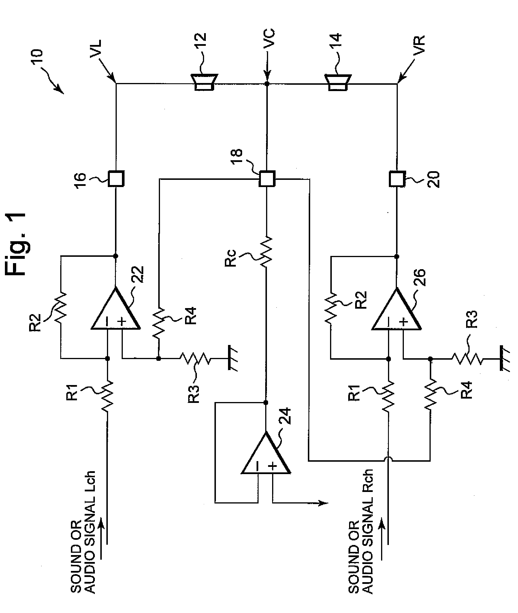
[0020]FIG. 1 schematically shows a configuration of a headphone amplifier circuit 10 according to the present embodiment. As shown in the same figure, the headphone amplifier circuit 10 includes a left output terminal 16, a center output terminal 18 and a right output terminal 20. A left channel headphone 12 corresponding to a load of the headphone amplifier circuit 10 is connected to the left output-terminal 16 and the center output terminal 18, and a right channel headphone 14 is connected to the right output terminal 20 and the center output terminal 18, respectively.

[0021]As shown in the same figure, the headphone amplifier circuit 10 includes an inverting amplifier 22 for amplifying a left audio signal Lch, an inverting amplifier 26 for amplifying a right audio channel Rch and an amplifier 24 that functions as a voltage follower.

[0022]As shown...


PUM


Abstract

The present invention provides a headphone amplifier circuit capable of canceling the influence of a parasitic resistance developed thereinside thereby to improve channel separation and increase output amplitude thereof. When audio signals respectively inputted to minus input terminals via resistors are amplified by inverting amplifiers each having a negative feedback circuit including a resistor and thereafter applied to input ends of left and right headphones, and the voltage of a preset potential is applied to each of output terminals of the headphones by an amplifier, a center output terminal of the amplifier and plus input terminals of the inverting amplifiers are connected to one another via resistors, and the plus input terminals of the inverting amplifiers are grounded via resistors respectively.

Description

BACKGROUND OF THE INVENTION[0001]The present invention relates to a headphone amplifier circuit.[0002]In a headphone amplifier circuit, sound or audio signals for right and left channels have heretofore been amplified by amplifiers and outputted the amplified to headphones (loads), respectively. In the present headphone amplifier circuit, there is a case in which noise is generated depending upon dc potentials at both ends of the left and right loads. A circuit that has cut dc components by providing coupling capacitors at output ends of left and right amplifiers has also been proposed.[0003]There has also been proposed a circuit in which an amplifier whose output end is connected between left and right channels is provided as a center amplifier to equalize dc-potentials at both ends of left and right channel loads, thereby realizing the cutting of noise caused by dc components at low current consumption without providing coupling capacitors at output ends of left and right amplifie...

Claims


Application Information

Patent Timeline
IPC IPC(8): H04R1/00H03F99/00
CPCH03F1/08H03F3/183H03F3/45475H04R3/00H03F2200/03H03F2203/45138H03F2203/45528H03F3/68
Inventor OGAWA, HIROFUMI
Owner LAPIS SEMICON CO LTD
Why Eureka
Try Eureka