Micro fuel cell, fabrication method thereof, and micro fuel cell stack using the same

a fuel cell and micro-chip technology, applied in the direction of fuel cell details, cable/conductor manufacturing, final product manufacturing, etc., can solve the problems of degradation of sofc performance, increasing demand for new mobile power sources, and inability to meet the energy density of mobile terminals, etc., to achieve enhanced reliability and long-term life span stability, and maintain structural stability

Inactive Publication Date: 2009-07-16
KOREA INST OF SCI & TECH
View PDF3 Cites 19 Cited by
  • Summary
  • Abstract
  • Description
  • Claims
  • Application Information

AI Technical Summary

Benefits of technology

The technical effect of this patent is that it describes how to create a small fuel cell that can withstand very hot temperatures without losing its structure or becoming less reliable over time. This is done by preventing certain materials from clumping together during use.

Problems solved by technology

The technical problem addressed in this patent text is developing a new process for creating complex structures within a fuel cell membrane that have both high temperature stability and compatibility with current technologies used for thin films and nanomachining. This is necessary because traditional methods for creating porous electrodes often result in damage to the overall integrity of the fuel cell under extreme temperatures and pressures typically encountered while operational.

Method used


Image

  • Micro fuel cell, fabrication method thereof, and micro fuel cell stack using the same
  • Micro fuel cell, fabrication method thereof, and micro fuel cell stack using the same
  • Micro fuel cell, fabrication method thereof, and micro fuel cell stack using the same

Examples


embodiment

[0117]Low stress silicon nitride was deposited with a thickness of 150 nm on Si wafer with a thickness of 300 μm according to LPCVD (FIG. 8A).

[0118]Next, one side of the silicon nitride-deposited wafer was patterned. In this case, positive photoresist (AZ 1512) was spin-coated and exposed to light by using a photomask having a square array of 520 μm×520 μm. The resulting structure was developed with a developer and silicon nitride was dry-etched (RIE) by using the remaining photoresist as a mask. The remaining photoresist was removed by using a photoresist remover.

[0119]Thereafter, Si was wet-etched for which a material of KOH:IPA:DIW=250 g:200 g:800 g was used as an etching solution and the etching was performed for five hours at 80° C. (FIG. 8C). The wafer is cut by the size of 2 cm×2 cm by using a dicing saw, and the cut substrate was washed by using an SPM (sulfuric acid+H2O2) solution or the like.

[0120]And then, TiN (20 nm) and Al (1 μm) layers were deposited on the silicon nit...


PUM

PropertyMeasurementUnit
Thicknessaaaaaaaaaa
Structureaaaaaaaaaa
Electric potential / voltageaaaaaaaaaa

Abstract

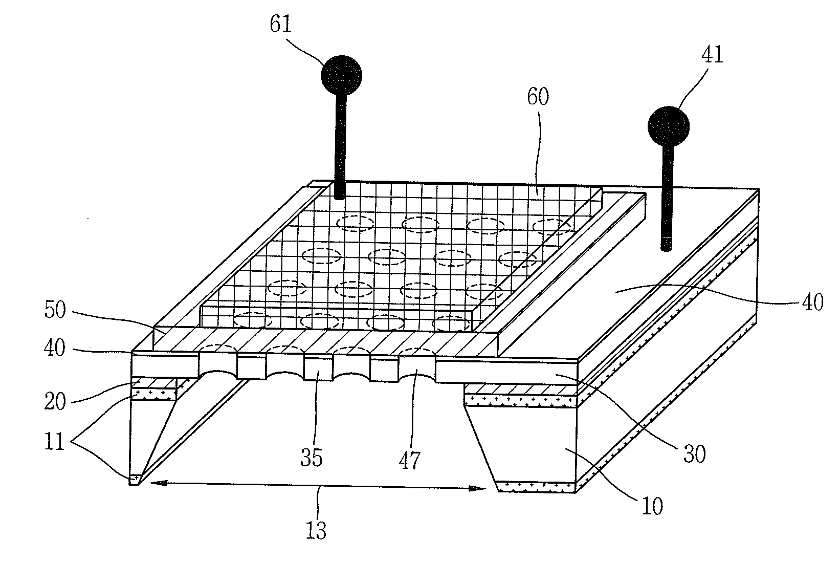
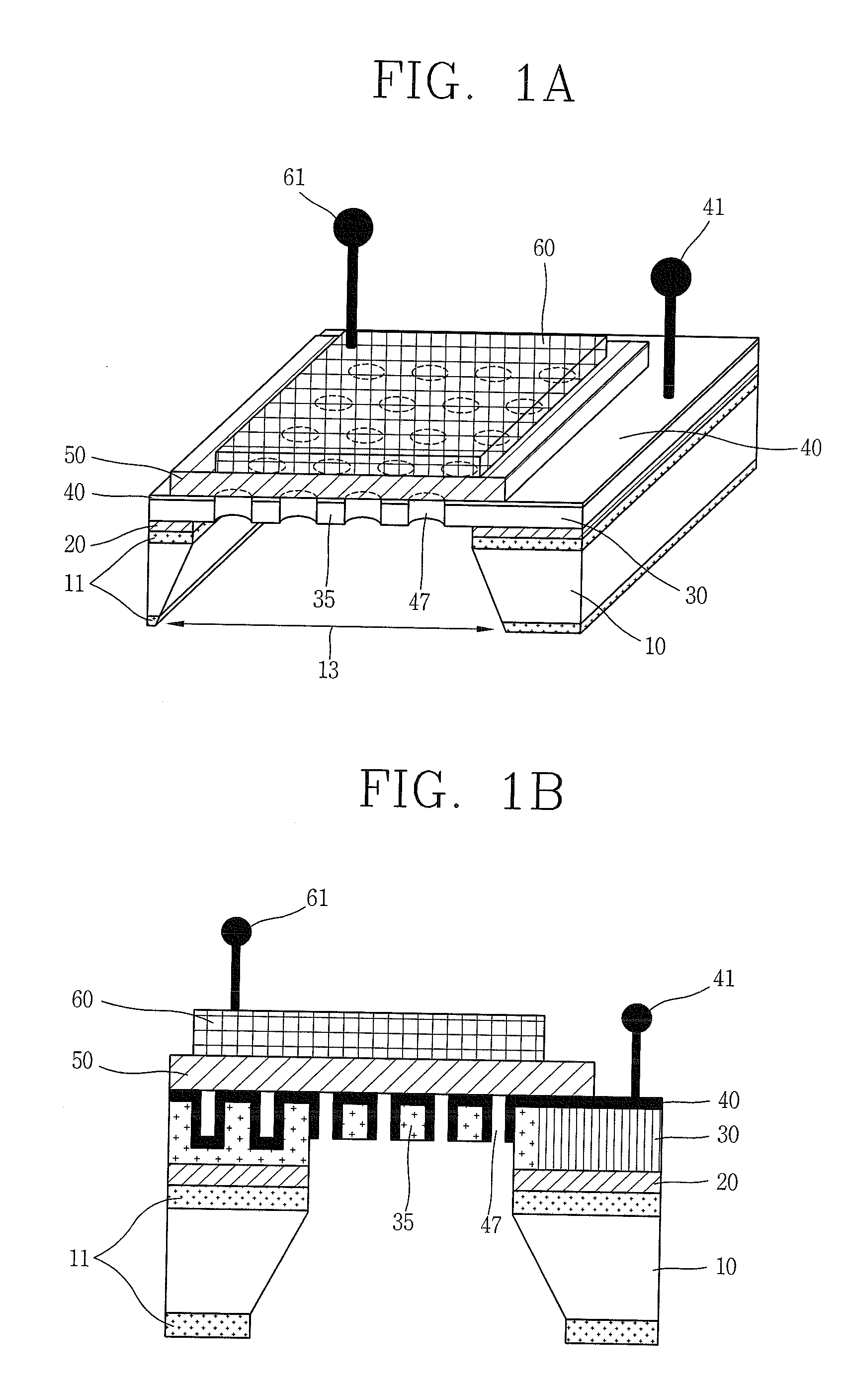
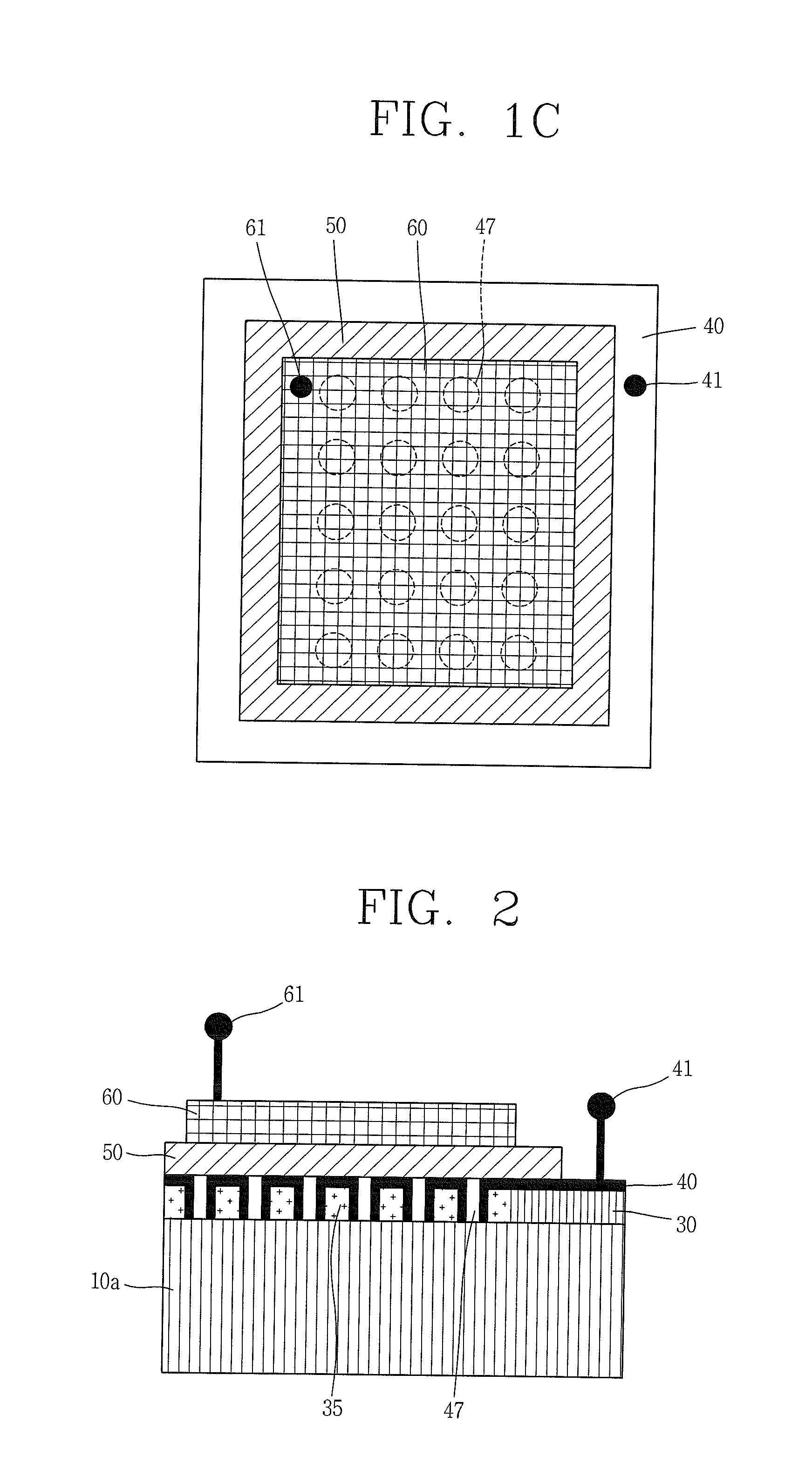
A micro cell fuel cell using a nano porous structure according to a thin film process and an anodizing process as a template for implementing a porous structure of an electrode, its fabrication method, and a micro fuel cell stack using the same are disclosed. The micro-fuel cell includes a solid electrolyte and first and second electrodes separately formed on the electrolyte, wherein at least one of the first and second electrodes is supported by a template having a plurality of nano pores formed by depositing, anodizing and etching a thin film, and is a porous electrode with nano pores formed at positions corresponding to the entirety or a portion of the plurality of nano pores formed on the template. The micro-fuel cell can be fabricated based on the thin film process, and unit cells can be highly integrated to implement a micro-fuel cell system generating a high voltage and a high current.

Description


Claims


Application Information

Patent Timeline
Owner KOREA INST OF SCI & TECH
Why Eureka
Try Eureka