Supercharge Your Innovation With Domain-Expert AI Agents!

Fuel cell separator

a fuel cell and separator technology, applied in the field of fuel cell separators, can solve the problems of unit cell b>2/b> being damaged undesirably, power generation output not being efficiently performed, and unit cell b>2/b> being lowered undesirably

Active Publication Date: 2009-07-16
HONDA MOTOR CO LTD
View PDF14 Cites 5 Cited by
  • Summary
  • Abstract
  • Description
  • Claims
  • Application Information

AI Technical Summary

Benefits of technology

[0013]The present invention has been made to solve the above problems, and an object of the present invention is to provide a fuel cell separator in which the desired sealing performance is achieved, and an exhaust gas is discharged smoothly and reliably.
[0019]According to the present invention, the circumferential length R of the sandwiching section and the width H of the bridge satisfy the relationship of 0.03≦H / R≦0.20. Therefore, the exhaust gas from the outer circumferential portion of the electrolyte electrode assembly is discharged smoothly and reliably, and the desired power generation output is obtained.
[0021]Further, according to the present invention, the circumferential length R of the sandwiching section and the outer diameter D of the manifold satisfy the relationship of 0.06≦D / R≦0.32. Therefore, the exhaust gas from the outer circumferential portion of the electrolyte electrode assembly is discharged smoothly and reliably, and the desired power generation output is obtained.

Problems solved by technology

Therefore, power generation is not performed efficiently, and the power generation output by the unit cells 2 may be lowered undesirably.
In the structure, when a tightening load is applied to the unit cells 2 and the separators 1 in the stacking direction to achieve the desired sealing performance of the fuel gas and the oxygen-containing gas, the unit cells 2 may be damaged undesirably by the excessive stress due to the tightening load.
Therefore, power generation is not performed efficiently, and the power generation output by the unit cells may be lowered undesirably.
Further, in the structure, when a tightening load is applied to the unit cells and the separators 5 in the stacking direction to achieve the desired sealing performance for preventing the leakage of the fuel gas and the oxygen-containing gas, the unit cells may be damaged undesirably by the excessive stress due to the tightening load.
Thus, exhaust gas is discharged non-uniformly or locally, or filled or stayed in local spots.
Therefore, power generation is not performed efficiently, and the power generation output is lowered undesirably.
Therefore, the electricity collection efficiency per unit area and the space efficiency are low.

Method used


Image

  • Fuel cell separator
  • Fuel cell separator
  • Fuel cell separator

Examples


first embodiment

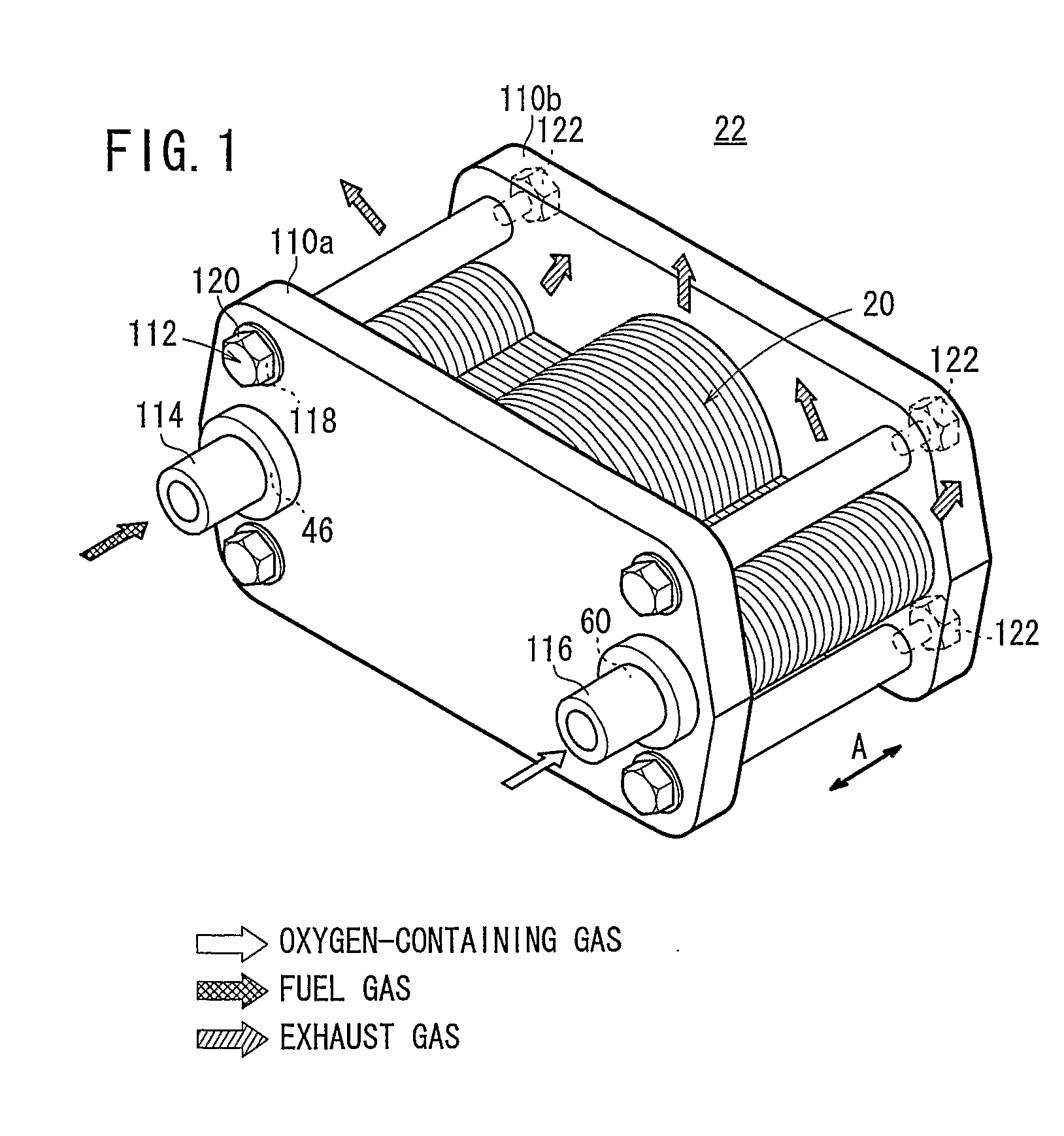
[0059]FIG. 1 is a perspective view schematically showing a fuel cell stack 22 formed by stacking a plurality of fuel cells 20 each including a fuel cell separator according to the present invention in a direction indicated by an arrow A.

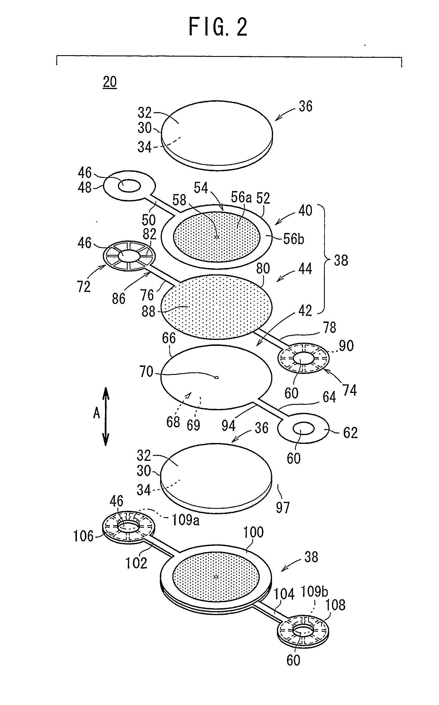
[0060]The fuel cell 20 is a solid oxide fuel cell (SOFC), and used in various applications, including stationary and mobile applications. As shown in FIGS. 2 and 3, the fuel cell 20 includes an electrolyte electrode assembly 36. The electrolyte electrode assembly 36 includes a cathode 32, an anode 34, and an electrolyte (electrolyte plate) 30 interposed between the cathode 32 and the anode 34. For example, the electrolyte 30 is made of ion-conductive solid oxide such as stabilized zirconia. The electrolyte electrode assembly 36 has a circular disk shape.

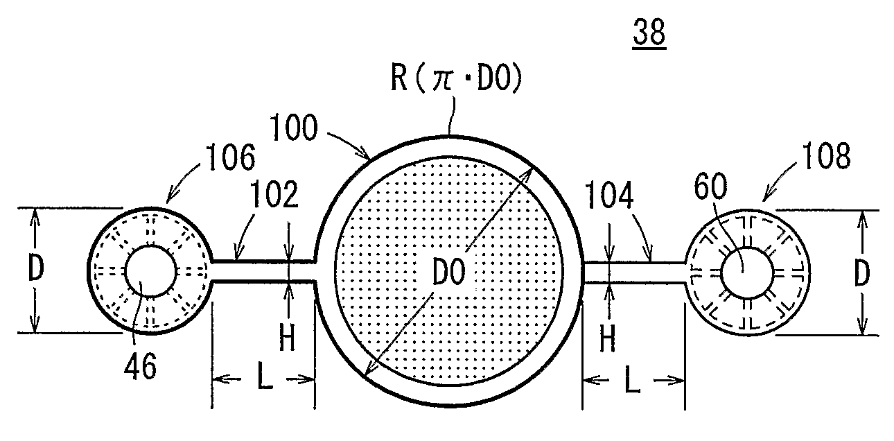
[0061]The fuel cell 20 is formed by sandwiching the electrolyte electrode assembly 36 between a pair of separators 38. As shown in FIG. 2, the separator 38 includes first and second plates 40, 42, and...

second embodiment

[0103]The fuel cell 130 includes a pair of separators 132 according to the present invention. Two electrolyte electrode assemblies 36 are sandwiched between the separators 132. As in the case of the separator 38, the separator 132 is made up of three plates (not shown). As shown in FIGS. 9 and 10, the separator 132 includes a first sandwiching section 100a having a circular disk shape and a second sandwiching section 100b having a circular disk shape for sandwiching the electrolyte electrode assemblies 36, respectively.

[0104]The first sandwiching section 100a and the second sandwiching section 100b are connected to a manifold 106 through bridges 102a, 102b. Further, the first sandwiching section 100a and the second sandwiching section 100b are connected to a manifold 108 through bridges 104a, 104b. Fuel gas supply channels 86a, 86b are formed in the bridges 102a, 102b, and oxygen-containing gas supply channels 94a, 94b are formed in the bridges 104a, 104b.

[0105]A fuel gas channel 5...

third embodiment

[0110]FIG. 11 is a perspective view schematically showing a fuel cell stack 142 formed by stacking a plurality of fuel cells 140 each including a fuel cell separator according to the present invention.

[0111]The fuel cell stack 142 is formed by stacking a plurality of fuel cells 140 in a direction indicated by the arrow A. Each of the fuel cells 140 has a circular disk shape having an outer curved section. End plates 144a, 144b are provided at opposite ends of the fuel cells 140 in the stacking direction, and a plurality of, e.g., eight tightening bolts 146 and nuts 148 are used for tightening components between the end plates 144a, 144b.

[0112]A circular fuel gas supply passage 46 extends through the center of the fuel cell stack 142 in the direction indicated by the arrow A, and the end plate 144a forms the bottom of the fuel gas supply passage 46 (see FIGS. 12 and 13). A plurality of, e.g., four exhaust gas channels 97 extending in the direction indicated by the arrow A are formed...


PUM

PropertyMeasurementUnit
angleaaaaaaaaaa
angleaaaaaaaaaa
circumferential lengthaaaaaaaaaa

Abstract

A fuel cell separator has a sandwiching section. The sandwiching section is connected to a fuel gas manifold through a bridge, and connected to an oxygen-containing gas manifold through a bridge. The circumferential length R of the sandwiching section, the width H of the bridges, the length L of the bridges, and the outer diameter D of the manifolds satisfies relationships of 0.03≦H / R≦0.20, 0.01≦L / R≦0.55, and 0.06≦D / R≦0.32.

Description

TECHNICAL FIELD[0001]The present invention relates to a fuel cell separator stacked on an electrolyte electrode assembly in a stacking direction. The electrolyte electrode assembly includes an anode, a cathode, and an electrolyte interposed between the anode and the cathode.BACKGROUND ART[0002]Typically, a solid oxide fuel cell (SOFC) employs an electrolyte of ion-conductive solid oxide such as stabilized zirconia. The electrolyte is interposed between an anode and a cathode to form an electrolyte electrode assembly. The electrolyte electrode assembly (unit cell) is interposed between separators (bipolar plates). In use, predetermined numbers of the electrolyte electrode assemblies and the separators are stacked together to form a fuel cell stack.[0003]As this type of the fuel cell, for example, a solid oxide fuel cell as disclosed in Japanese Laid-Open Patent Publication No. 3-129675 (hereinafter referred to as the first conventional example) is known. As shown in FIG. 35, the fuel...

Claims


Application Information

Patent Timeline
Patent Type & Authority Applications(United States)
IPC IPC(8): H01M2/14
CPCH01M8/0228H01M8/0252H01M8/0258H01M8/04089H01M8/2425H01M8/248Y02T90/32H01M2250/10H01M2250/20Y02E60/50Y02B90/14Y02E60/525H01M2008/1293H01M8/2432H01M8/2457H01M8/2483Y02B90/10Y02T90/40
Inventor TSUNODA, TADASHIYOKOKAWA, AYATOSHIKUROISHI, TOMOYOSHI
Owner HONDA MOTOR CO LTD
Features
  • R&D
  • Intellectual Property
  • Life Sciences
  • Materials
  • Tech Scout
  • Unparalleled Data Quality
  • Higher Quality Content
  • 60% Fewer Hallucinations
Learn More