
Intra-oral camera for diagnostic and cosmetic imaging

Inactive Publication Date: 2009-07-16
CARESTREAM DENTAL TECH TOPCO LTD
View PDF33 Cites 56 Cited by
  • Summary
  • Abstract
  • Description
  • Claims
  • Application Information

AI Technical Summary

Benefits of technology

[0011]A feature of the present invention is that it utilizes a common optical system for both diagnostic and cosmetic imaging. An advantage of the present invention is that it provides a single imaging instrument for a range of dental applications.

Problems solved by technology

However, with such an approach, any unwanted specular reflection produces false positive results in reflectance imaging.
Moreover, with the various illumination embodiments disclosed, the illumination directed toward a tooth or other diagnostic object is not uniform, since the light source is in close proximity to the diagnostic object.
Notably, hand-held shade-matching systems are not designed for ease of access to any but the front teeth.
Conventional shade-matching techniques can match tooth color acceptably, but may not provide enough data for providing a substitute tooth that appears real and exhibits some amount of translucence.
This is largely because conventional cosmetic imaging systems are directed primarily to color matching, but provide insufficient information on tooth translucency and surface texture.
This results in an uneven distribution of light and reduces the overall accuracy of the system for measuring tooth translucency.
Specular reflection can be undesirable for both diagnostic and cosmetic imaging, but must be compensated in different ways for each type of imaging.

Method used


Image

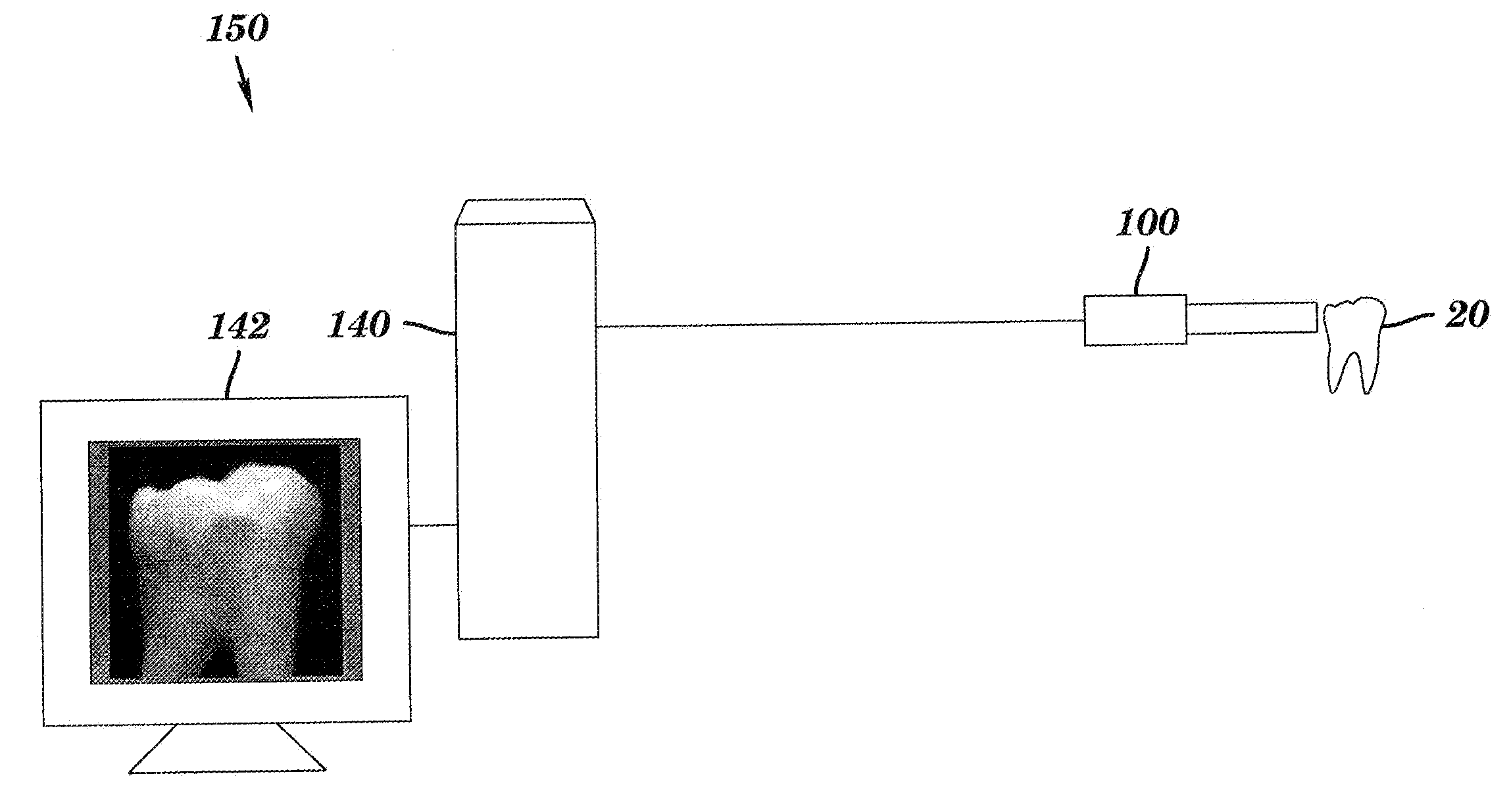
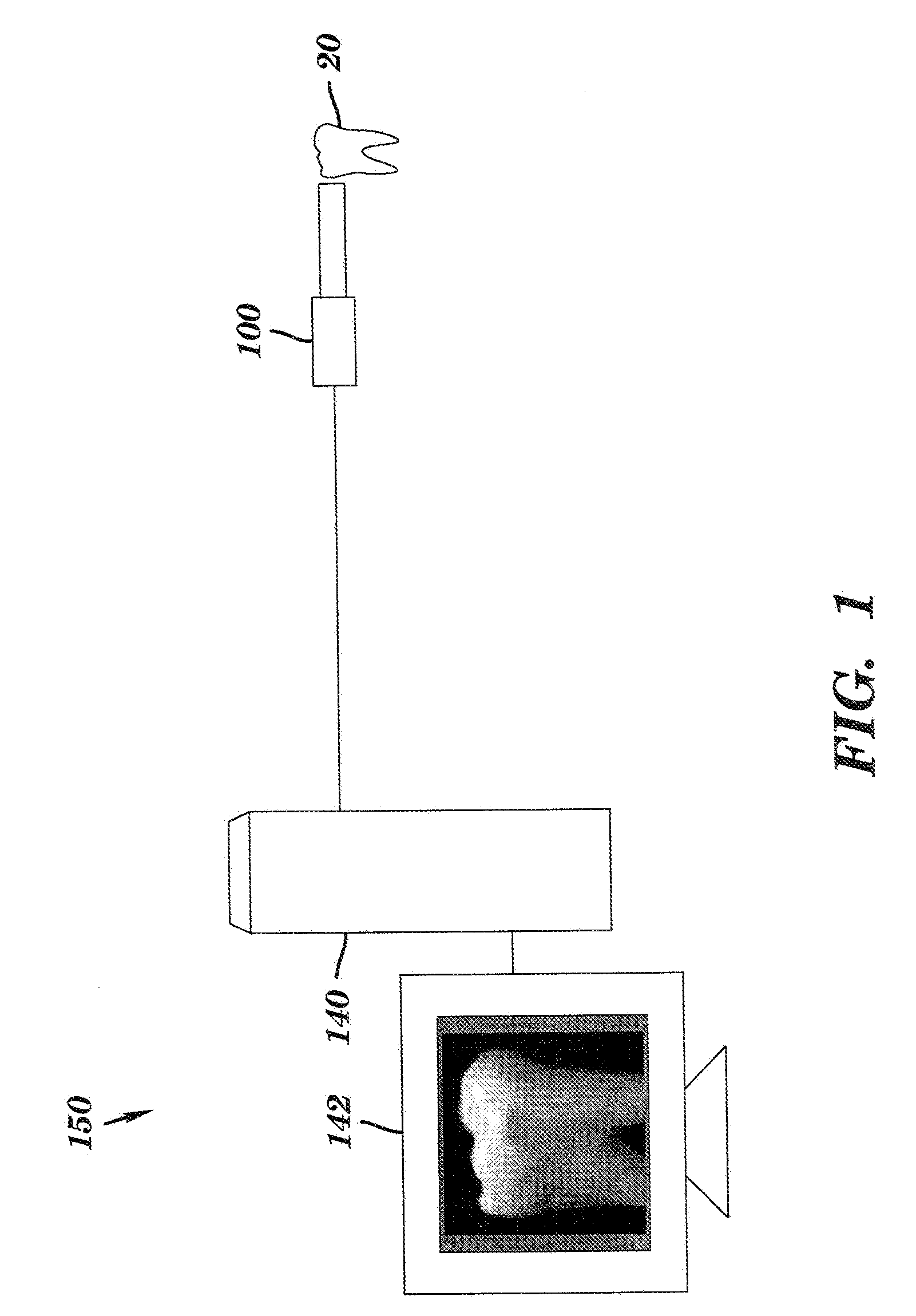
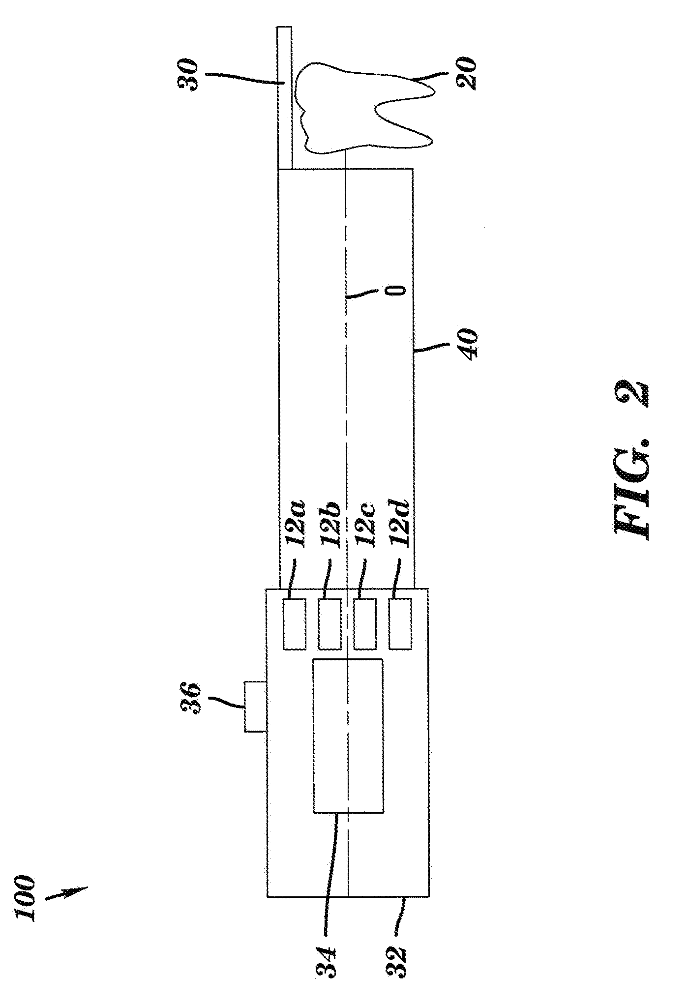
  • Intra-oral camera for diagnostic and cosmetic imaging
  • Intra-oral camera for diagnostic and cosmetic imaging
  • Intra-oral camera for diagnostic and cosmetic imaging

Examples


Embodiment Construction

[0030]The method and apparatus of the present invention combine both diagnostic and cosmetic functions to provide a versatile intra-oral imaging system for use by dental practitioners. As noted earlier in the background section, there are significant differences in requirements between diagnostic and cosmetic imaging, including different light source and optical system requirements, appropriate compensation for specular reflection, and different image processing. Moreover, cosmetic imaging itself is complex and can involve more than merely shade matching. In addition to matching color, accurate cosmetic imaging also requires that additional information on more subtle tooth features be obtained, including translucency, surface texture, gloss, and other characteristics.

[0031]Commonly assigned U.S. Patent Application Publication No. 2007 / 0099148, previously mentioned and incorporated herein by reference, describes a diagnostic imaging approach that combines both fluorescence and reflec...


PUM


Abstract

An apparatus for obtaining images of a tooth comprises at least one image sensor disposed along an optical axis to take polarized reflectance image and fluorescence image, at least one broadband illumination apparatus for reflectance imaging, and a narrow-band ultraviolet illumination apparatus for fluorescence imaging. In order to remove the specular reflection, one or more polarization elements are disposed along the optical axis. A filter is disposed along the optical axis to block narrow-band ultraviolet light, and a switch for selecting one of the operation modes.

Description

CROSS-REFERENCE TO RELATED APPLICATIONS[0001]The present application is related to U.S. Patent Application Publication 2007 / 0099148, entitled METHOD AND APPARATUS FOR DETECTION OF CARIES, filed Oct. 31, 2005 in the names of Victor C. Wong, Rongguang Liang, and Donna Rankin-Parobek; U.S. Patent Application Publication 2007 / 0248931, entitled OPTICAL DETECTION OF DENTAL CARIES filed Apr. 21, 2006 in the names of Victor C. Wong, Rongguang Liang, Michael A. Marcus, Paul O. McLaughlin, and David Patton; and U.S. patent application Ser. No. 11 / 623,804, entitled SYSTEM FOR EARLY DETECTION OF DENTAL CARIES filed Jan. 17, 2007 in the names of Peter D. Burns, Victor C. Wong, Mark E. Bridges and Rongguang Liang.FIELD OF THE INVENTION[0002]This invention generally relates to methods and apparatus for dental imaging and more particularly relates to an intra-oral camera apparatus that includes capabilities for caries detection as well as for shade matching.BACKGROUND OF THE INVENTION[0003]Digital ...

Claims


Application Information

Patent Timeline
IPC IPC(8): A61C19/00
CPCA61B1/0638A61B1/24A61B5/0088A61B1/0646A61B1/043A61B1/0607A61B1/00186A61B1/0625
Inventor LIANG, RONGGUANGINGLESE, JEAN-MARC
Owner CARESTREAM DENTAL TECH TOPCO LTD
Learn More