Flanged interbody device

a flanged interbody and fusion technology, applied in the field of medical devices, can solve the problems of increased pain and potentially neurologic complications, pseudarthrosis or failure of fusion, and the failure of the anterior column support, so as to increase the torsional stability and prevent the effect of subsiden

Inactive Publication Date: 2009-07-16
CUSTOM SPINE INC
View PDF3 Cites 53 Cited by
  • Summary
  • Abstract
  • Description
  • Claims
  • Application Information

AI Technical Summary

Benefits of technology

[0007]In view of the foregoing, an embodiment herein provides a flanged interbody device to prevent subsidence while increasing torsional stability. The flanged interbody device includes an implant to be inserted in a vertebral body. The implant includes a first lateral portion, a second lateral portion, a top wall, a bottom wall and teeth positioned on the top wall and the bottom wall. The second lateral portion is positioned opposite to the first lateral portion. The top wall and the bottom wall are attached to the first lateral portion and the second lateral portion. The bottom wall is positioned opposite to the top wall. The first lateral portion further includes at least one flange surface and the second lateral portion further includes an opening. The top wall further includes a plurality of holes. The implant may include a plurality of cuts positioned between the first lateral portion and the second lateral portion.

Problems solved by technology

Anterior column support may fail if the interbody spacer subsides through the vertebral endplates.
Consequently, this may lead to increased pain and potentially neurologic complications.
Furthermore, it may also lead to pseudarthrosis or failure of fusion.
Conventional implants tend to provide a limited amount of surface area.
Conventional implants also generally do not include any supporting structure which can prevent decoupling of the implant from the vertebrae, which gives rise to subsidence of the implants.
Some implants also suffer from the disadvantage of involving piercing and tapping of vertebral endplates for insertion.
Additionally, restoration of natural curvature of the spine is also very difficult.
The longer implants may be clinically specified but the wider implants are not desirable as the increased width involves more of facet scissoring which leads to a decrease in stability.

Method used


Image

  • Flanged interbody device
  • Flanged interbody device
  • Flanged interbody device

Examples


Embodiment Construction

[0023]The embodiments herein and the various features and advantageous details thereof are explained more fully with reference to the non-limiting embodiments that are illustrated in the accompanying drawings and detailed in the following description. Descriptions of well-known components and processing techniques are omitted so as to not unnecessarily obscure the embodiments herein. The examples used herein are intended merely to facilitate an understanding of ways in which the embodiments herein may be practiced and to further enable those of skill in the art to practice the embodiments herein. Accordingly, the examples should not be construed as limiting the scope of the embodiments herein.

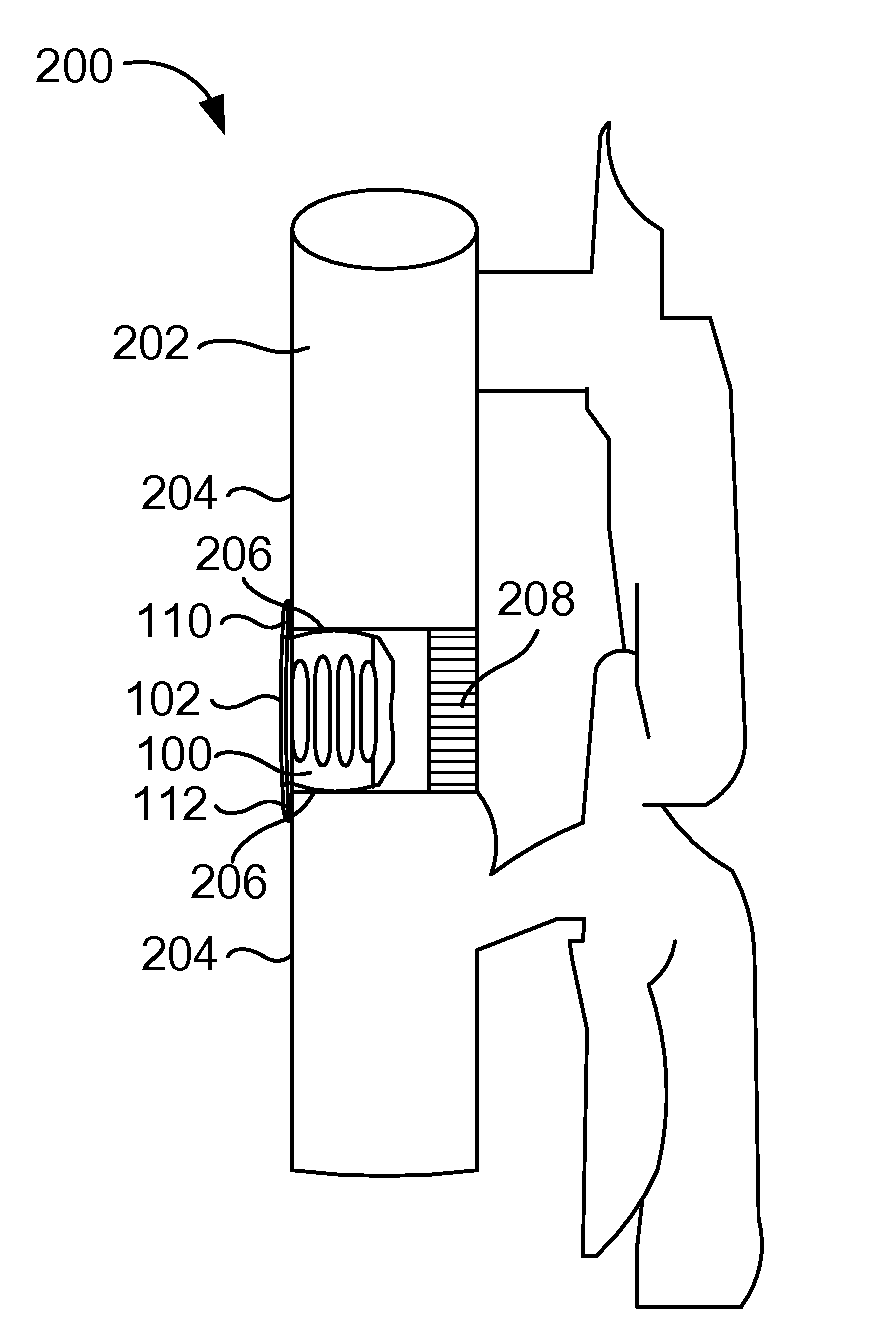
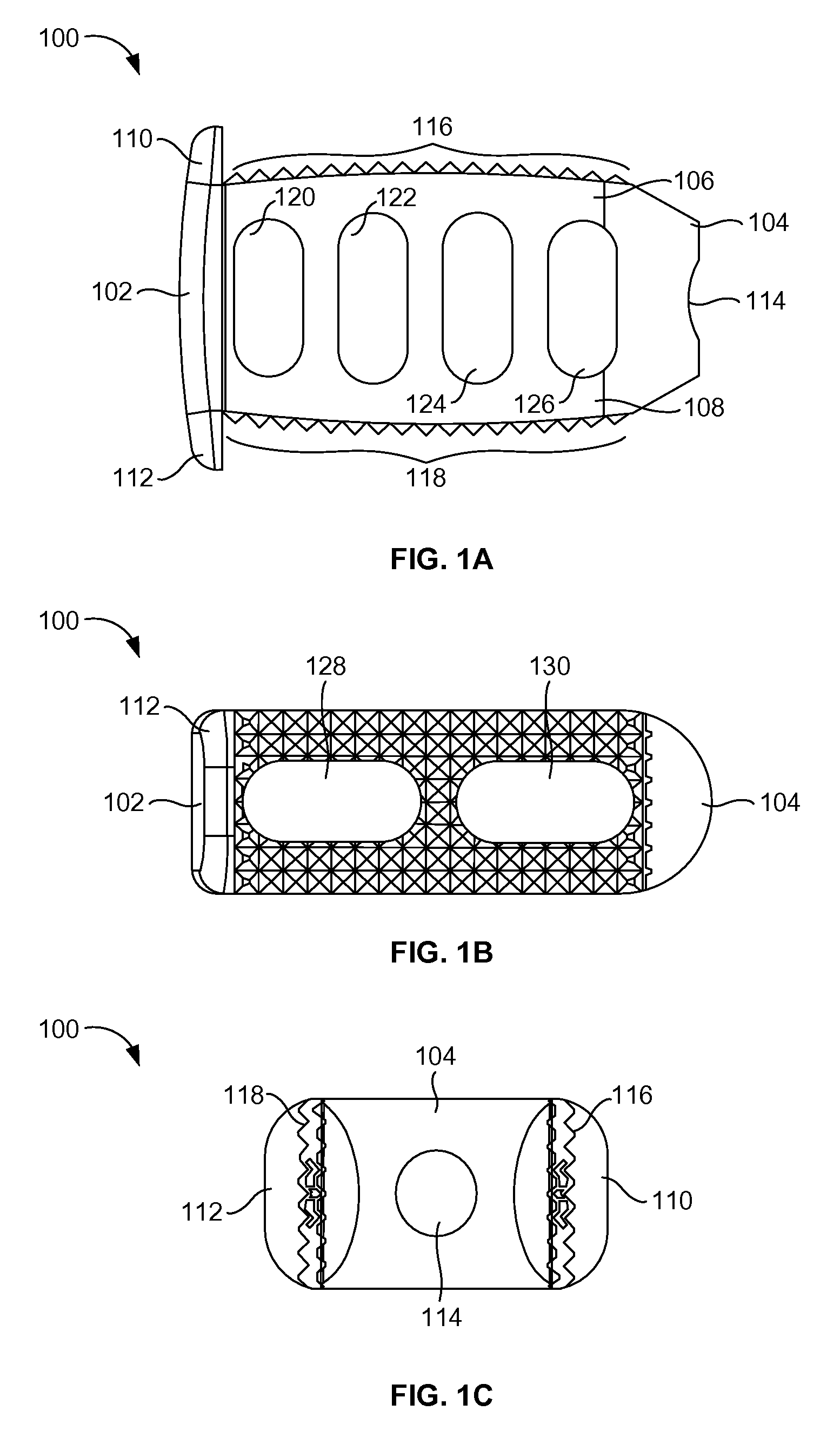
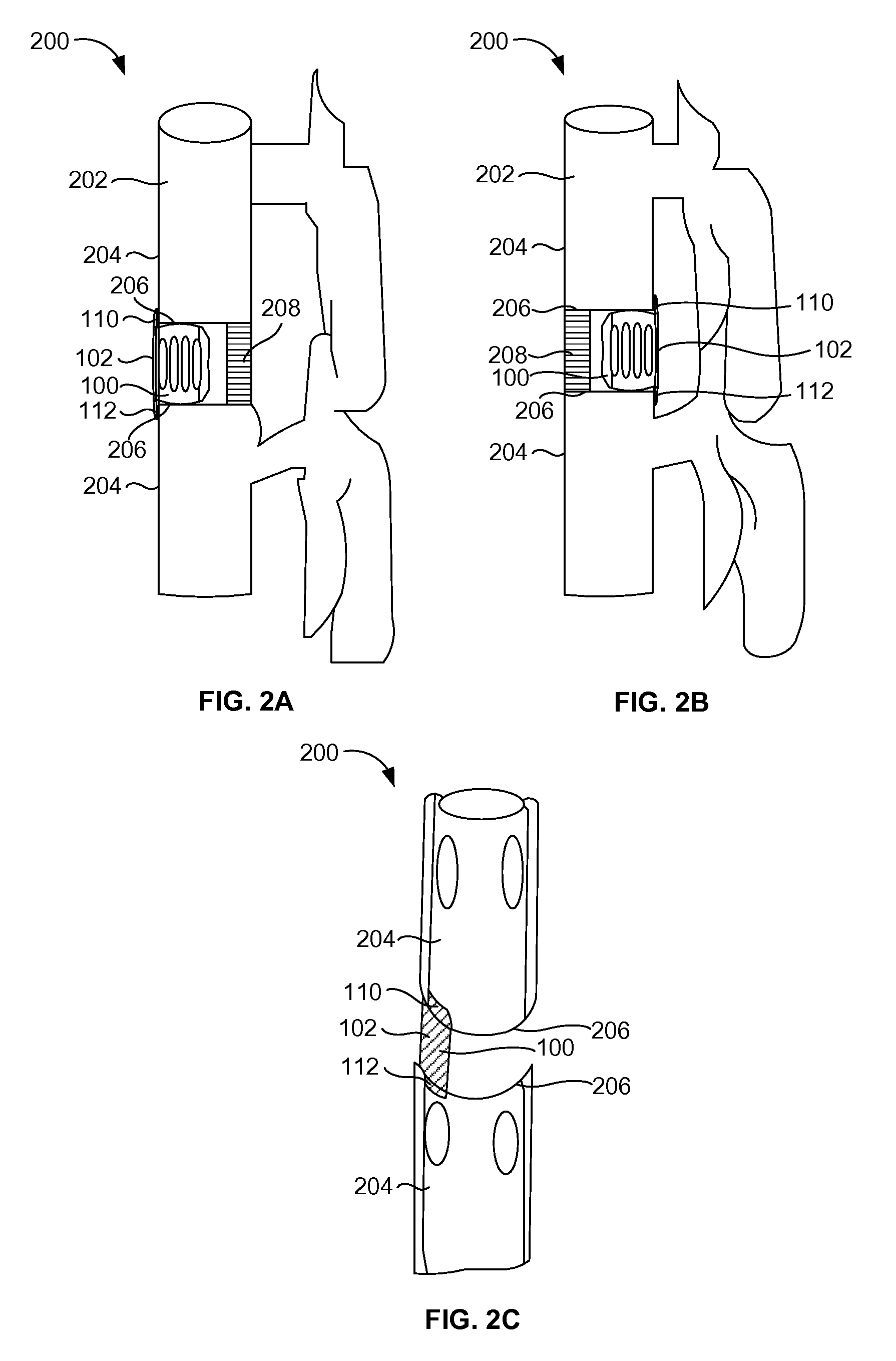
[0024]As mentioned, there remains a need for a new interbody device to prevent subsidence while increasing torsional stability. The embodiments herein achieve this by providing an interbody device that uses a flange to allow the lateral vertebral body to participate in load bearing and shear an...


PUM


Abstract

An interbody implant including a first lateral portion, a second lateral portion positioned opposite to the first lateral portion, a top wall having a plurality of holes, a bottom wall positioned opposite to the top wall, and teeth positioned on the top wall and the bottom wall. The top wall and the bottom wall are attached to the first lateral portion and the second lateral portion. The first lateral portion further includes at least one flange surface and the second lateral portion further includes an opening. The at least one flange surface may be configured to couple to a peripheral wall of the vertebral body and may be adapted to provide at least one of a torsional property, an axial property, and a shear property to the implant. The teeth may be adapted to provide a mechanical interlock between the implant and vertebral endplates of the vertebral body.

Description

BACKGROUND[0001]1. Technical Field[0002]The embodiments herein generally relate to medical devices, and more particularly, to a flanged interbody device used during orthopedic surgeries.[0003]2. Description of the Related Art[0004]Anterior lumbar interbody fusion (ALIF), posterior lumbar interbody fusion (PLIF), and transforaminal lumbar interbody fusion (TLIF) are common spinal fusion procedures for fusing and stabilizing vertebrae. In these procedures, interbody spacers are placed within the intervertebral disc space. They are responsible for transmitting load across the disc space from one vertebra to the other. The spacer serves as a temporary column or structural support until fusion occurs. The loads across the interbody spacer include the weight of the person and any load being carried by the person.[0005]Peripheral walls of the vertebrae are the strongest bones on vertebral endplates whereas subchondral bone (e.g., bone beneath cartilage) is the soft and weaker bone. Anterio...

Claims


Application Information

Patent Timeline
Patent Type & Authority Applications(United States)
IPC IPC(8): A61F2/44
CPCA61F2/447A61F2002/30112A61F2002/30576A61F2230/0004A61F2002/30841A61F2002/448A61F2002/30784
Inventor MCCLELLAN, III, JOHN W.STAMM, SARAH
Owner CUSTOM SPINE INC
Why Eureka
Try Eureka