Vacuum Dust Collector

a vacuum cleaner and dust collector technology, applied in vacuum cleaners, household cleaners, tableware washing/rinsing machines, etc., can solve the problems of easy fluttering of dust in the air, user discomfort, easy for users, etc., and achieve the effect of occupying spa

Inactive Publication Date: 2009-07-23
TSAI SAM
View PDF8 Cites 26 Cited by
  • Summary
  • Abstract
  • Description
  • Claims
  • Application Information

AI Technical Summary

Benefits of technology

[0005]The primary objective of the present invention is to provide a vacuum dust collector which has a shape fits or corresponding to the place where it is located. Thus, space usage of the vacuum dust collector can be more efficiency.

Problems solved by technology

But dust flies in the air easily when swept, and the user might feel uncomfortable.
However, it is not easy for the user to collect all dust and dump into a waste container precisely, results in the poor efficiency and high demanding efforts.
However, the poor control over usage results in inconvenience for the user while cleaning.
Nevertheless it is only required the user press the switch, and the vacuum motor turned on without an auxiliary instrument to assure whether the filter is installed or not, even the vacuum motor may be damaged by dust and dirt.
Moreover, it is hard to arrange space efficiently for the shape of the vacuum dustpan may occupy too much room or not fit perfectly to where it is located.

Method used


Image

  • Vacuum Dust Collector
  • Vacuum Dust Collector
  • Vacuum Dust Collector

Examples


Embodiment Construction

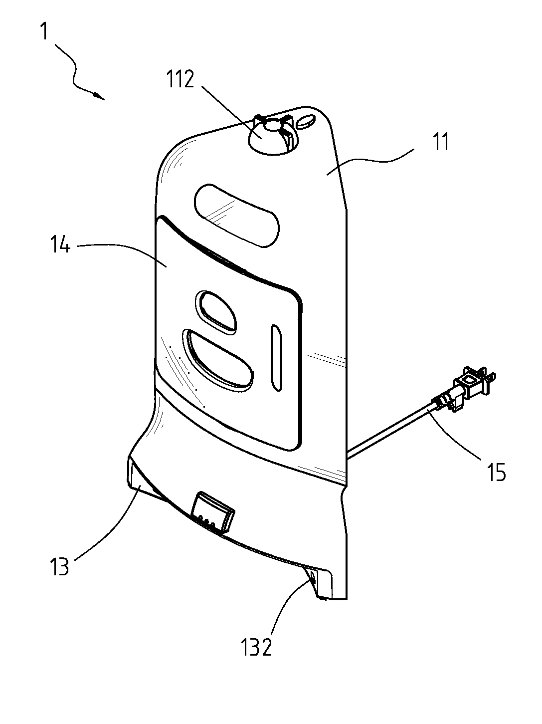
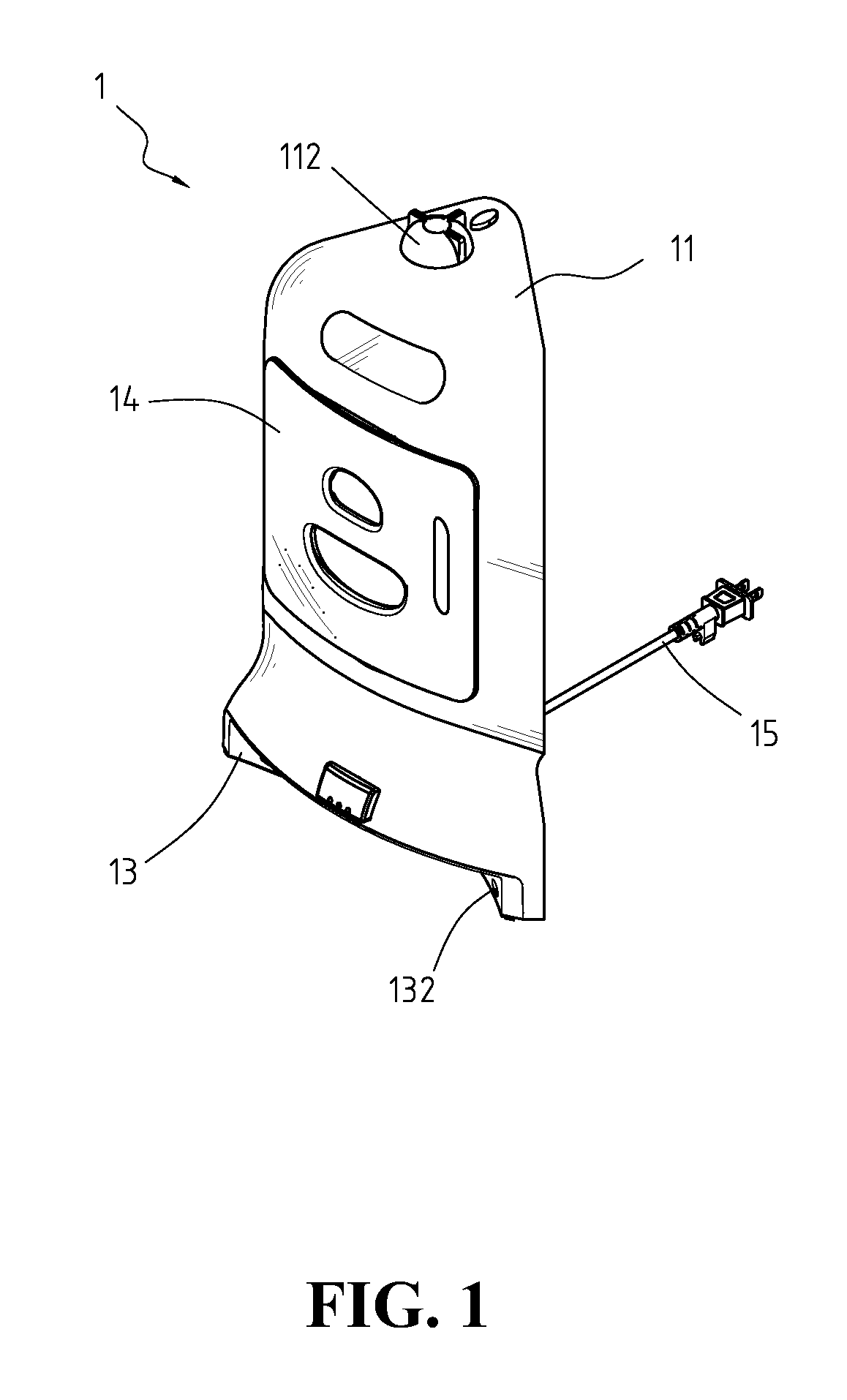
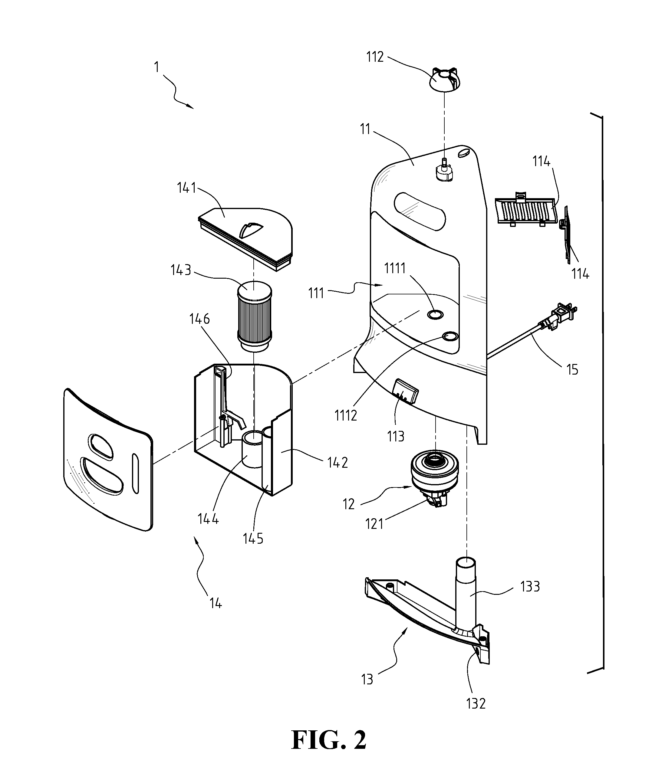
[0023]Referring to FIG. 1 and FIG. 2, illustrates the perspective view and the exploded view of the present invention, respectively. A vacuum dust collector 1 comprises a housing 11, a suction generator 12, a bottom cover 13, a dust container 14 and a power cord 15, wherein the housing 11 includes a concaved space 111, a control knob 112, an outlet port 1111 and an inlet port 1112 mounted in the bottom of the concaved space 111. The control knob 112 is set on the top surface of the housing 11 and electrically connected to the suction generator 12. In addition, the control knob 112 is used to switch the operation mode of the vacuum dust collector 1.

[0024]Furthermore, there is a suction side and an exhausted side in the suction generator 12 placed under the concaved space 111 of the housing 11. The suction generator 12 is connected to the outlet port 1111 of housing 11 by the suction side. Subsequently, the suction generator 12 includes a motor 121 and a fan (unshown). The motor 121 a...


PUM


Abstract

A vacuum dust collector comprising a housing including a concaved space inside and a control knob on the top; an suction generator placed under the concaved space; a bottom cover, covered at the bottom of the housing, including a dust inlet and at least one sensor; and a dust container, disposed in the concaved space, including a cover, a chamber, a filter, an outlet pipe, an inlet pipe, and a latch. Moreover, the shape of the housing is corresponding to the place where it is located, and the latch is pressed by the filter disposed on the outlet pipe of dust container to allow the cover to be eclipsed on the chamber.

Description

FIELD OF THE INVENTION[0001]The present invention relates to a vacuum cleaner, more particularly to a vacuum dust collector.BACKGROUND OF THE INVENTION[0002]Conventionally, the cleaning procedure requires the user to sweep the debris and dust into a pile and use a collection device such as dustpan to pick up the debris and dust. But dust flies in the air easily when swept, and the user might feel uncomfortable. However, it is not easy for the user to collect all dust and dump into a waste container precisely, results in the poor efficiency and high demanding efforts.[0003]According to U.S. Pat. No. 6,671,924 B1 which is published on Jan. 6, 2004, titled “Vacuum Dustpan” disclosed a vacuum dustpan having a housing with an inlet to the level of the floor surface into which dust and debris can be directed. The vacuum dustpan is equipped with a vacuum motor which transfer the debris to a collection chamber within the housing. However, the poor control over usage results in inconvenience...

Claims


Application Information

Patent Timeline
Patent Type & Authority Applications(United States)
IPC IPC(8): A47L5/38
CPCA47L7/0047
Inventor TSAI, SAM
Owner TSAI SAM
Why Eureka
Try Eureka