Eureka AIR delivers breakthrough ideas for toughest innovation challenges, trusted by R&D personnel around the world.

Panelling system

Inactive Publication Date: 2009-07-23
GIBSON KELLY +1
View PDF13 Cites 19 Cited by
  • Summary
  • Abstract
  • Description
  • Claims
  • Application Information

AI Technical Summary

Benefits of technology

[0013]the joint when fastened prevents pivoting movement of the strips to a position in which the angle between the strips at the front surface of the panel is greater than 180 degrees;

Problems solved by technology

This construction is time consuming and relatively inaccurate so that gaps can be exposed leading to an unattractive appearance.
Often such panels are formed from laminated or other non-wood materials and hence are not accepted as a high quality wood product.
This arrangement as disclosed was proposed for use with rectangular panels of solid wood or for deck strips and as such was not suitable for high quality interior flooring.

Method used


Image

  • Panelling system
  • Panelling system
  • Panelling system

Examples


Embodiment Construction

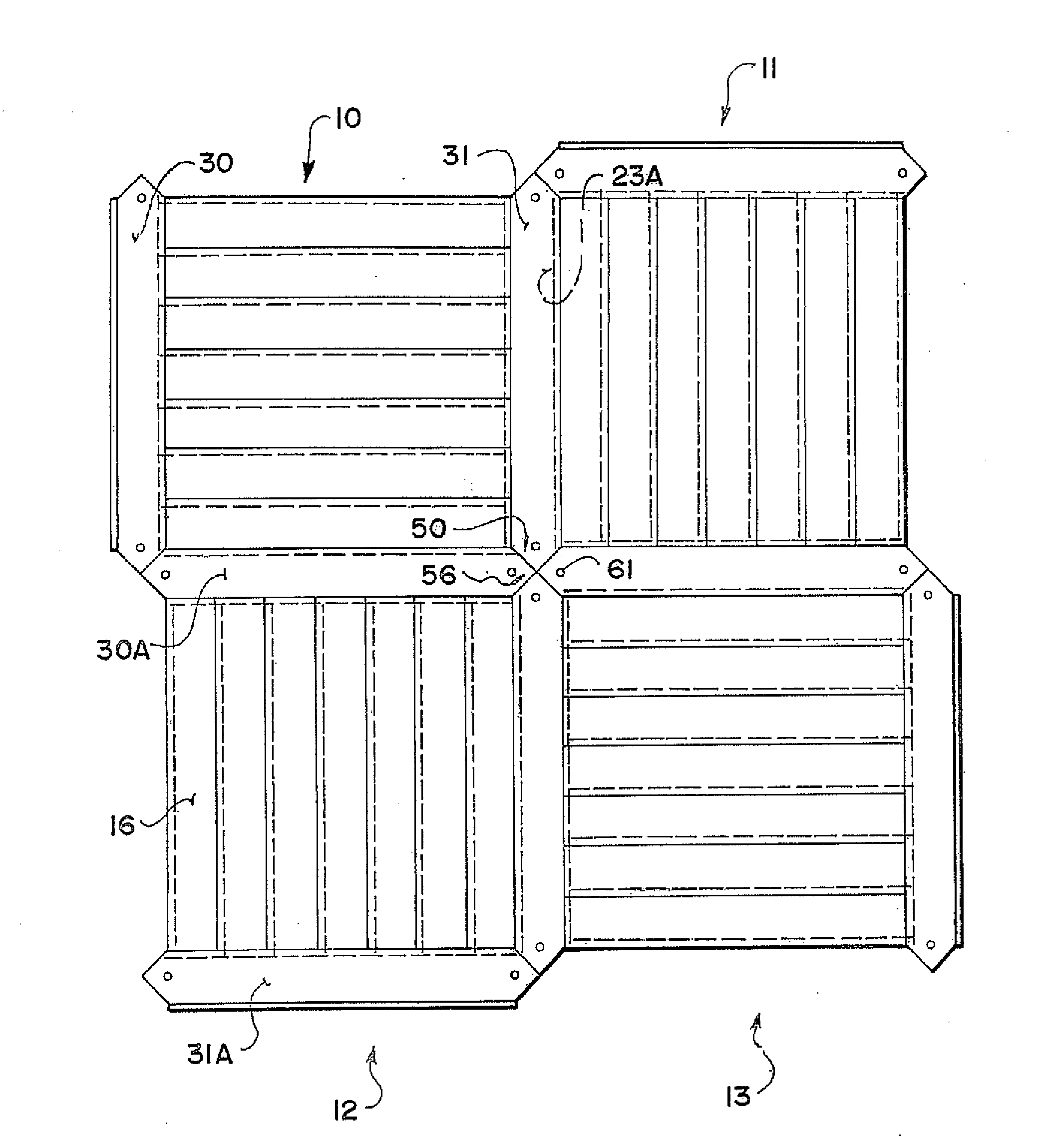
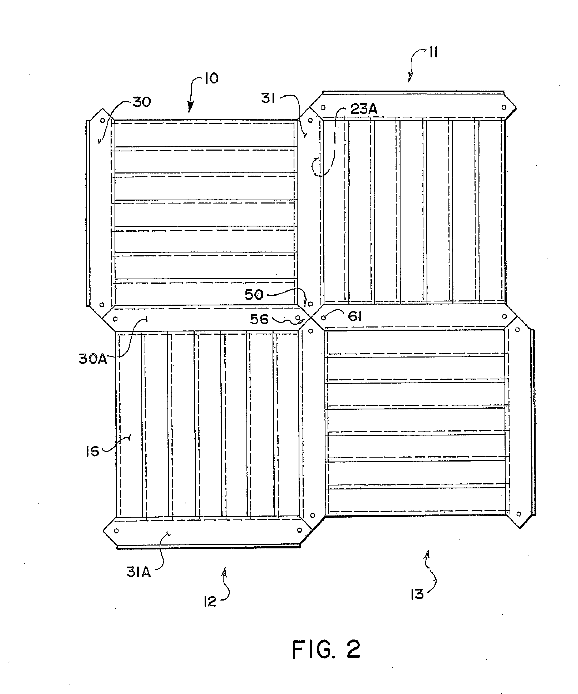
[0042]Reference is made to the above published application of Gibson which shows and describes the details of the panels with the dividing strips and the interconnection between the four corners of the panels.

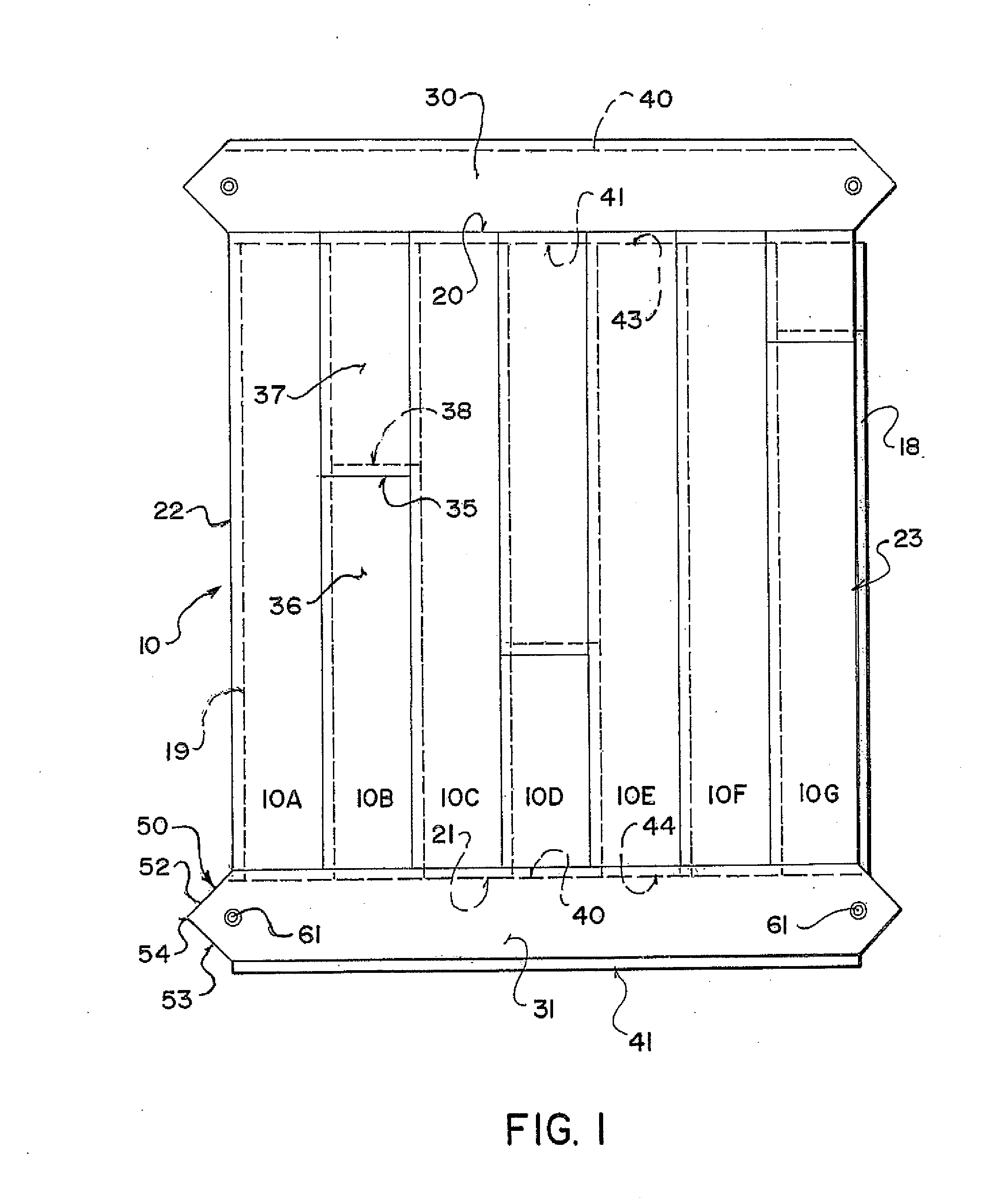
[0043]The arrangement described herein comprises a floor system defined by a series of panel members, four of which are shown at 10 through 13. Each of the panel members has a top surface 16 defining a floor surface on which the user walks and providing an attractive appearance as described hereinafter. Each of the panel members includes a bottom surface 17 for sitting on a sub floor of a conventional nature.

[0044]Each of the panel members is formed from a plurality of side by side main strips 10A to 10G which are connected together side by side to form an initial panel portion which has four side edges so that for example the panel 10 has side edges 20 and 21 which form a first pair of opposed side edges and side edges 22 and 23 which form a second pair of opposed side edges.

[...


PUM


Abstract

A panelling system preferably for floors is defined by a series of panels each formed of a plurality of tongue and groove main floor plank strips arranged side edge to side edge and cut to a common length with a tongue along one cut edge and a groove along the other. At the edges are attached edge strips formed also from the flooring planks with tongue and groove and fastened together to form a common panel member for transportation and installation. The outwardly facing edge has a tongue or groove for mating with a groove or tongue of a next adjacent panel. The strips are fastened by pins or corrugated plates from the rear or by a bonded sheet material on the rear. The strips may include tongue and groove joints of the snap fastening type where the connection of each strip to the next in the assembled panel can be simply by way of an adhesive tape over the rear surface of the joint.

Description

[0001]This invention relates to a panelling system defined by a plurality of inter-engaging panels. The system is primarily designed for flooring but can be used for other surfaces requiring to be paneled with an attractive layer of a covering material formed in individual panels. The system is primarily designed for use with panels formed of wood but other materials can be used either to form the entire panel or a part of the panel.BACKGROUND OF THE INVENTION[0002]Various techniques have been proposed for the manufacture of wood panel flooring. Conventionally wood panel flooring is formed as tongue and groove planks which are arranged edge to edge so that the tongue of one projects into a groove of the next. This construction is time consuming and relatively inaccurate so that gaps can be exposed leading to an unattractive appearance.[0003]Floor panels in rectangular shape have been proposed which generally again connect one to the next using a tongue and groove arrangement so as t...

Claims


Application Information

Patent Timeline
IPC IPC(8): E04F13/08E04C2/38
CPCE04F15/02E04F15/16E04F2201/0115E04F2201/0511E04F2201/026E04F2201/043E04F2201/0153E04F15/02038E04F2201/07
Inventor GIBSON, KELLYHOARD, LEN
Owner GIBSON KELLY
Why Eureka
Eureka Blog
Learn More