Eureka AIR delivers breakthrough ideas for toughest innovation challenges, trusted by R&D personnel around the world.

Method and device for determination of the mobility of a hip joint prosthesis

Inactive Publication Date: 2006-11-23
AESCULAP AG
View PDF7 Cites 9 Cited by
  • Summary
  • Abstract
  • Description
  • Claims
  • Application Information

AI Technical Summary

Benefits of technology

[0008] When the pivoting movement of the femur is limited by one of said stops, in other words by direct contact of bony structures, by contact of prosthetic parts with bony structures or by contact of prosthetic parts with one another, a further pivoting of the femur with respect to the hip bone can then only be achieved in that pivoting takes place about the contact point, and this inevitably leads to the spherical joint surface being lifted from the bearing cup, i.e. the spacing increases between the central points of the bearing cup, on the one hand, and of the spherical joint surface, on the other hand, which points coincide with normal fitting of the spherical joint surface in the bearing cup. Thus, if it is determined that these central points move apart from one another, in other words a luxation occurs in the hip

Problems solved by technology

Owing to this mounting, the femur can be pivoted in all directions with respect to the hip bone, this pivoting movement is limited, on the one hand, by the surrounding soft tissue and, on the other hand, this pivoting movement can be limited in that the bony structures of the hip joint and femur strike against one another or against parts of the prosthesis.
This limitation of the pivoting movement may be undesired, and it is therefore necessary to establish during the operation whether the desired mobility of the femur with respect to the hip bone is achieved after insertion of the hip joint prosthesis.

Method used


Image

  • Method and device for determination of the mobility of a hip joint prosthesis
  • Method and device for determination of the mobility of a hip joint prosthesis
  • Method and device for determination of the mobility of a hip joint prosthesis

Examples


Embodiment Construction

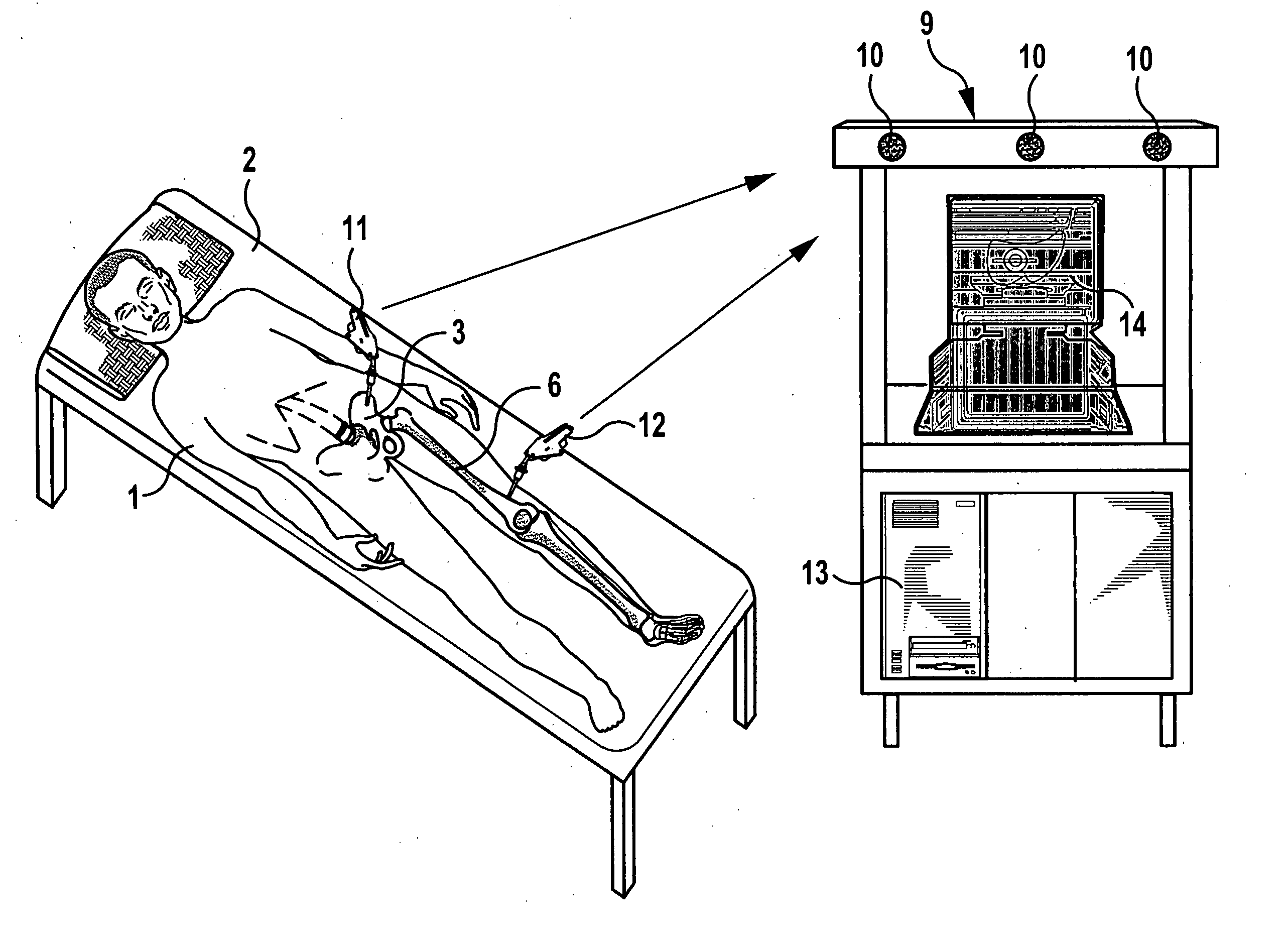
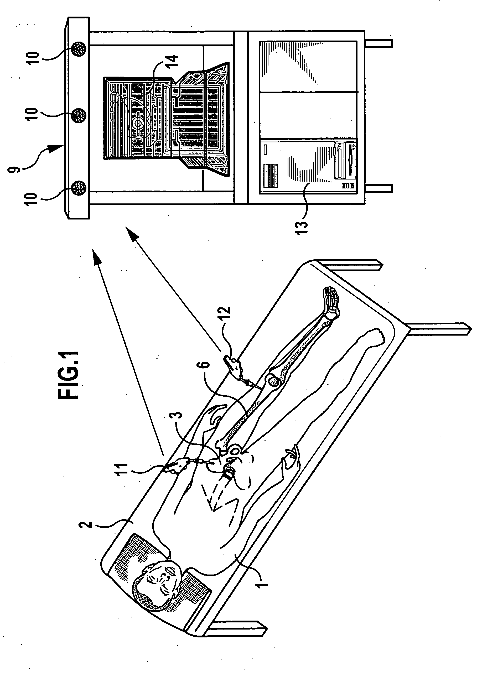
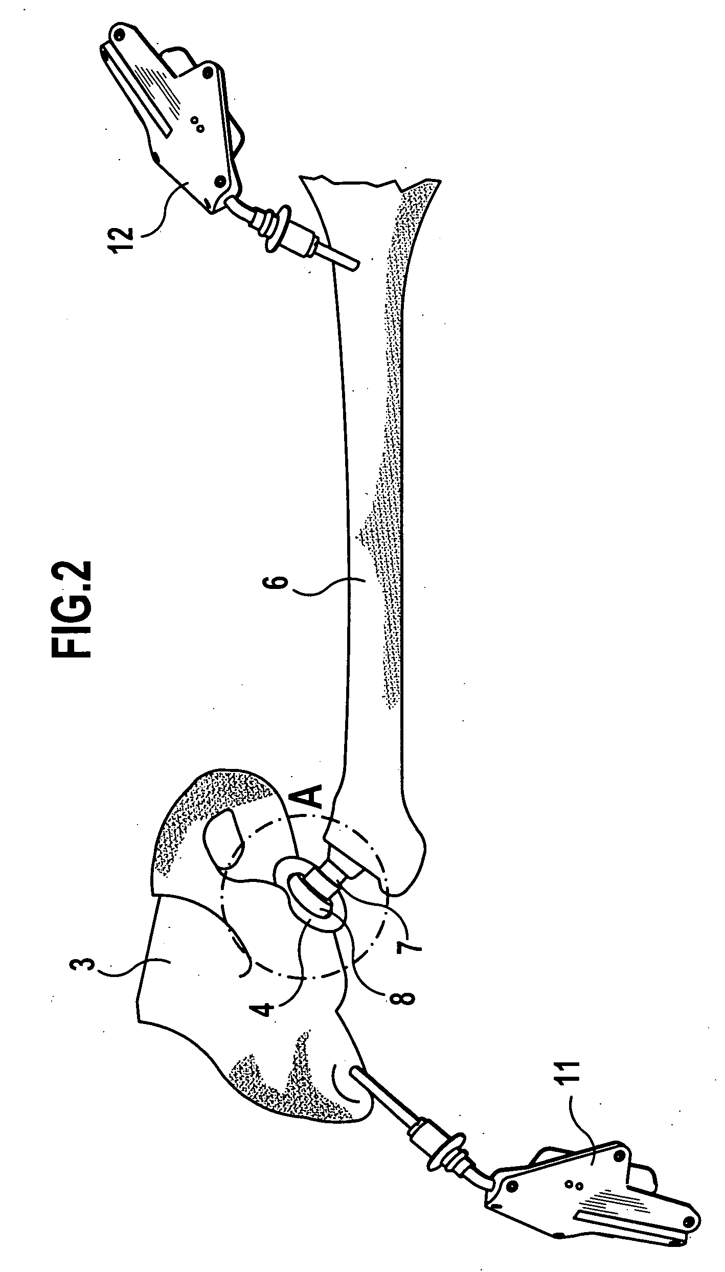
[0028] In an operating theatre, a patient 1 lies on an operating table 2, where an artificial hip joint is to be inserted. For this purpose, a bearing cup 4 with a substantially semi-spherical concave bearing surface 5 is inserted in the hip bone 3 and a prosthetic shaft 7 is inserted in the femur 6, the prosthetic shaft carrying a convex, spherical joint surface 8 on its end projecting out of the femur 6. This spherical joint surface 8 has the same diameter as the concave spherical bearing surface 5 and engages in the latter such that the central points of the spherical joint surface 8 and the bearing surface 5 coincide; a ball joint is formed which makes pivoting of the femur 6 possible in all directions with respect to the hip bone 3.

[0029] In order to be able to follow these pivoting movements, a navigation system 9 is provided, which continually determines the position, in other words the location and the orientation of the hip bone 3 and femur 6 in the space. The navigation s...


PUM


Abstract

A method for determination of the mobility of a hip joint prosthesis is proposed, comprising a bearing cup that can be inserted in the hip bone and a prosthetic shaft that can be inserted in the femur and is pivotally mounted by a spherical joint surface in the bearing cup, which is characterised in that the femur with the prosthetic shaft is pivoted as far as possible in various directions, in that it is determined whether the central point of the bearing cup and the central point of the spherical joint surface move apart from one another during this process, and in that, for each pivoting direction, the maximum pivoting angle is thus determined, at which the central points begin to move apart from one another. A device for carrying out this method is also proposed.

Description

[0001] This application is a continuation of international application number PCT / EP03 / 10779 filed on Sep. 27, 2003. [0002] The present disclosure relates to the subject matter disclosed in international application PCT / EP03 / 10779 of Sep. 27, 2003, which is incorporated herein by reference in its entirety and for all purposes.BACKGROUND OF THE INVENTION [0003] The invention relates to a method for determination of the mobility of a hip joint prosthesis comprising a bearing cup that can be inserted in the hip bone and a prosthetic shaft that can be inserted in the femur and is pivotally mounted by a spherical joint surface in the bearing cup. [0004] The invention also relates to a device for carrying out this method. [0005] During insertion of hip joint prostheses, a bearing cup is generally inserted in the hip joint and a prosthetic shaft is inserted in the femur, this prosthetic shaft engages with a spherical joint surface in the bearing cup, which is also spherical, so the central...

Claims


Application Information

Patent Timeline
IPC IPC(8): A61B17/56A61B5/103A61B5/107A61B19/00A61F2/32A61F2/34A61F2/36A61F2/46G01S5/18G01S17/87
CPCA61B5/103G01S17/875A61B5/4528A61B19/5244A61B2019/461A61B2019/467A61B2019/502A61B2019/508A61B2019/5255A61B2019/5272A61F2/32A61F2/34A61F2/36A61F2/4657A61F2/4684A61F2002/3493A61F2002/3611A61F2002/4632A61F2002/4658A61F2002/4668A61F2002/4688A61B5/107A61B34/20A61B2034/102A61B2034/108A61B2034/2055A61B2034/2072A61B2090/061A61B2090/067
Inventor LEITNER, FRANCOISMOLLARD, BENOIT
Owner AESCULAP AG
Why Eureka
Eureka Blog
Learn More