
Hinge lid container

a lid container and hinge technology, applied in the direction of lids, non-removable lids/covers, packaging, etc., can solve the problems of limited visible exterior surface area and small size of standard hinge lid cigarettes packs

Inactive Publication Date: 2009-07-23
PHILIP MORRIS USA INC
View PDF44 Cites 29 Cited by
  • Summary
  • Abstract
  • Description
  • Claims
  • Application Information

AI Technical Summary

Benefits of technology

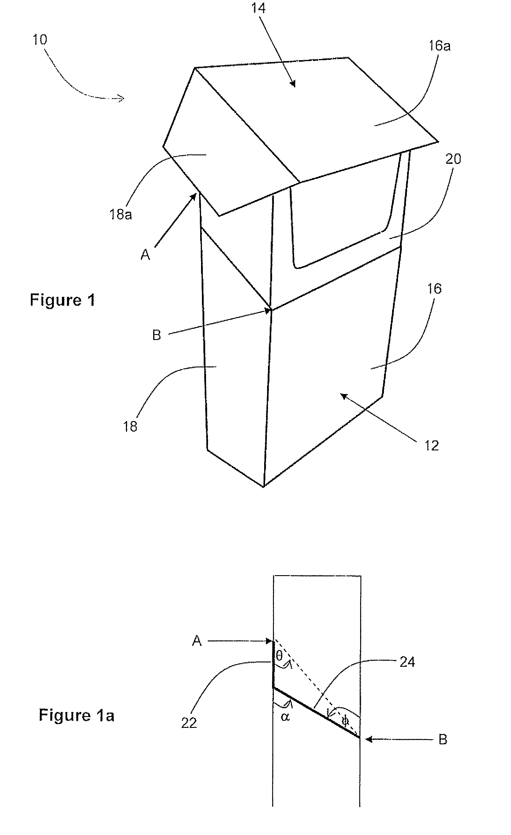
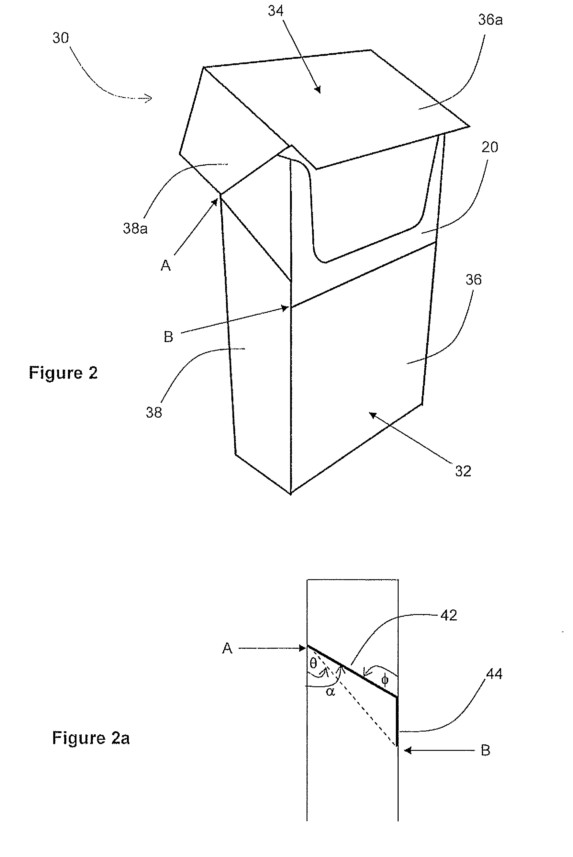
[0019]Although it may be desirable to minimize the angle θ in order to increase the visible internal surface area of containers according to the invention, it is also preferable if the angle φ is as high as possible. This is because the larger the angle φ, the stronger and more durable the lower portion of the side walls of the lid portion become. Furthermore, the larger the angle φ, the more rigid the lower section of the lid portion becomes.
[0020]It is particularly preferable if the angle α defined between the line of abutment extending across the side wall of the container and the rear edge of the side wall of the box portion of the container is also maximized. By increasing the angle α, the increased strength and durability described above with reference to the angle φ are also obtained for the upper portion of the side walls of the box portion. Depending on the shape of the line of abutment between point A and point B, the angle α may be the same as, or different to the angle φ.
[0021]The present invention provides containers in which the form of the line of abutment between point A and point B may be varied such that the angle θ can be kept relatively low, whilst the angles φ and α can be similar to, or greater than the corresponding angles in known hinge lid packs. The strength and rigidity of containers according to the invention need not, therefore, be compromised in order to obtain the greater internal surface area.
[0028]Preferably, each side wall of the container is formed from an inner wall and an overlying outer wall. The line of abutment extending along the inner wall between point A and point B may be different to, or the same as the line of abutment extending along the outer wall. Preferably, the line of abutment extending along the inner wall between point A and point B is the same shape as the line of abutment extending along the outer wall, but is vertically offset therefrom. A vertical offset may, advantageously, be employed to strengthen the rear wall of the box portion and the front wall of the lid portion.
[0029]The line of abutment between the lower edge of the front wall of the lid portion and the upper edge of the front wall of the box portion is preferably a straight, substantially horizontal line. The front wall of the box portion may include a cut out at the upper edge thereof to expose the inner packaging underneath. Alternatively, or in addition, the front wall of the lid portion may include a cut out at the lower edge thereof. Where a cut out is provided, there will typically be no abutment of the lower edge of the lid portion with the upper edge of the box portion and the line of abutment will therefore be broken. The provision of a cut out may assist the consumer in opening the lid portion.
[0031]Preferably, the front wall of the inner frame is provided with a cut out portion at the upper edge thereof. This enables more convenient access to the consumer goods within the container, without significantly reducing the surface area of the front wall of the inner frame.

Problems solved by technology

However, standard hinge lid cigarette packs are relatively small in size and have a limited visible exterior surface area for displaying such information.

Method used


Image

  • Hinge lid container
  • Hinge lid container
  • Hinge lid container

Examples


Embodiment Construction

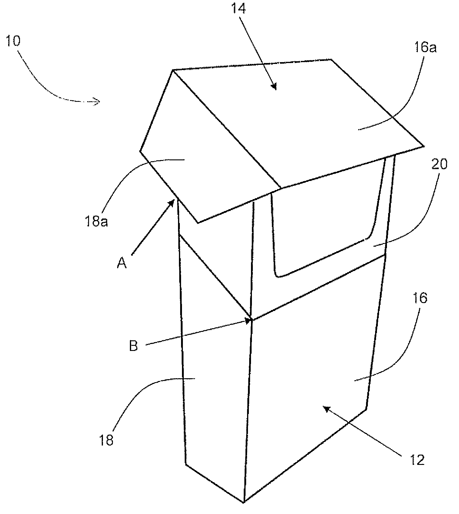
[0045]The hinge lid container 10 shown in FIG. 1 is a rectangular parallelepiped and comprises a lower box portion 12 and an upper lid portion 14 that is hinged to the lower box portion 12 along a hinge fine extending substantially horizontally along the rear wall of the container. The level of the hinge line is indicated in FIG. 1 at point “A”.

[0046]The box portion 12 has a front wall 16, a left side wall 18, a right side wall, a rear wall, and a bottom wall. The rear wall of the box portion 12 extends above the side walls thereof so that the upper edge of the rear wall is offset from the upper free edges of the side walls. The upper edge of the rear wall of the box portion is defined by the hinge line.

[0047]The lid portion 14 has a front wall 16a, a left side wall 18a, a right side wall, a rear wall and an upper wall. The side walls 18a of the lid portion extend beyond the rear wall thereof so that the lower free edge of each side wall is offset from the lower edge of the rear wal...


PUM


Abstract

A hinge lid container for smoking articles having a front wall, a rear wall and opposed side walls extending therebetween comprises: a box portion; and a lid portion hinged to the box portion along a hinge line extending across a rear wall of the container. At each side wall of the container, the angle □ between the front edge of the side wall of the lid portion and the lower edge thereof is greater than the angle □ defined between the rear edge of the side wall and a straight line extending between a first point (A) where the hinge line meets the side wall and a second point (B) where the upper edge of a front wall of the box portion meets the side wall.

Description

CROSS-REFERENCE TO RELATED APPLICATION[0001]This application claims priority under 35 U.S.C. §119 to European Application No. 08250259.2, filed Jan. 21, 2008, the entire content of which is hereby incorporated by reference.BACKGROUND OF THE DISCLOSURE[0002]The present invention relates to a novel hinge lid container, which finds particular application as a container for elongate smoking articles such as cigarettes.[0003]It is known to package elongate smoking articles and other consumer goods in containers formed from folded laminar blanks. Elongate smoking articles, such as cigarettes and cigars, are commonly sold in hinge lid packs having a box portion for housing the smoking articles and a lid portion connected to the box portion about a hinge line extending across the rear wall of the container. Such packs are typically constructed from one-piece laminar cardboard blanks. In use, the lid portion is pivoted about the hinge line to open the pack and so gain access to the smoking a...

Claims


Application Information

Patent Timeline
IPC IPC(8): B65D43/16
CPCB65D85/1045B65D85/1056
Inventor LUTZIG, BODO W.SNYDER, TONY
Owner PHILIP MORRIS USA INC
Learn More