
Semiconductor device and method for manufacturing a semiconductor device

Inactive Publication Date: 2009-07-23
INFINEON TECH AUSTRIA AG
View PDF8 Cites 10 Cited by
  • Summary
  • Abstract
  • Description
  • Claims
  • Application Information

AI Technical Summary

Benefits of technology

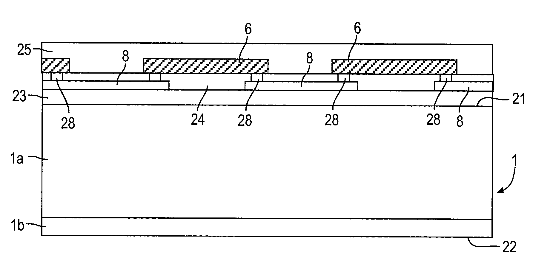
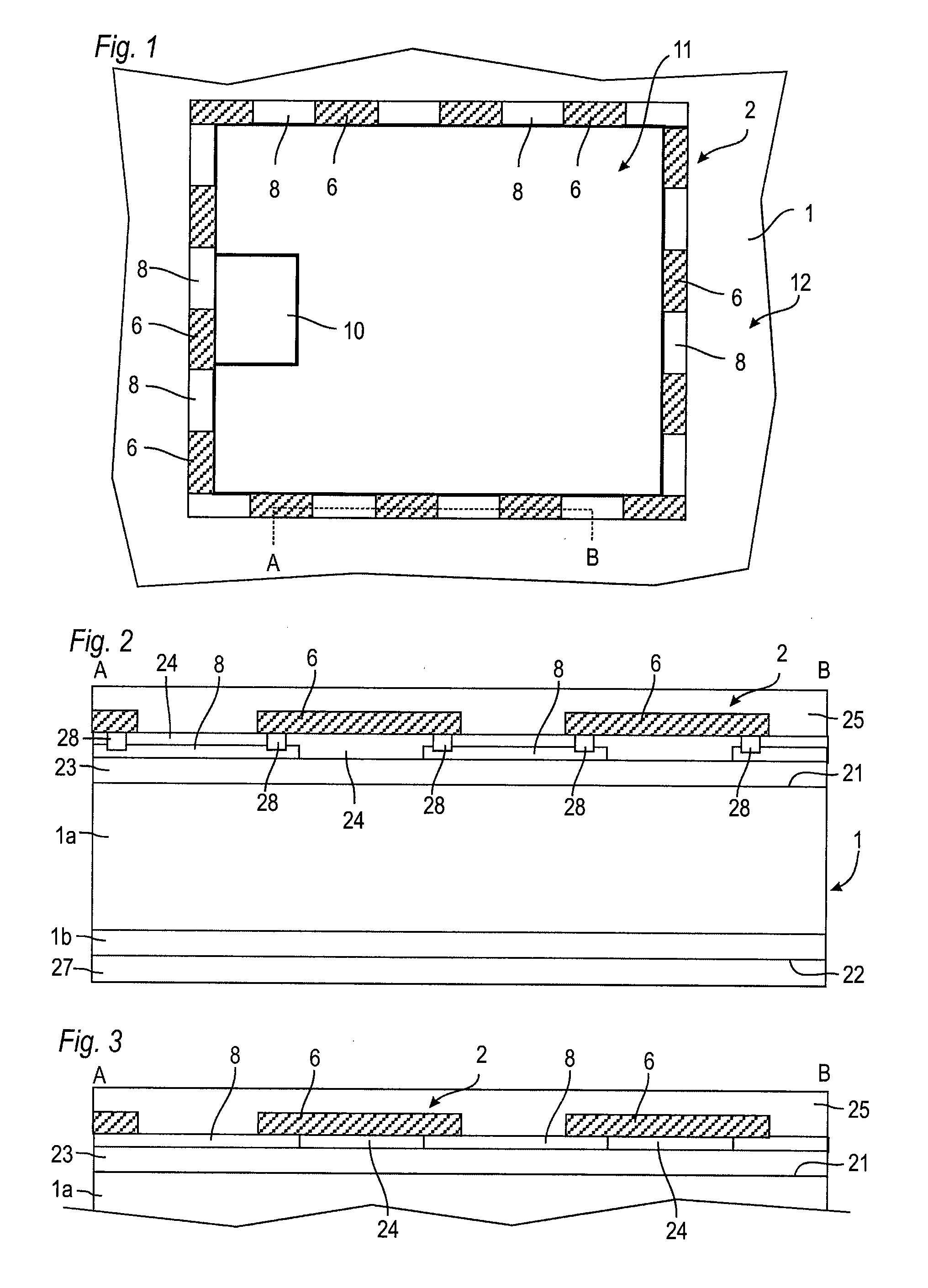
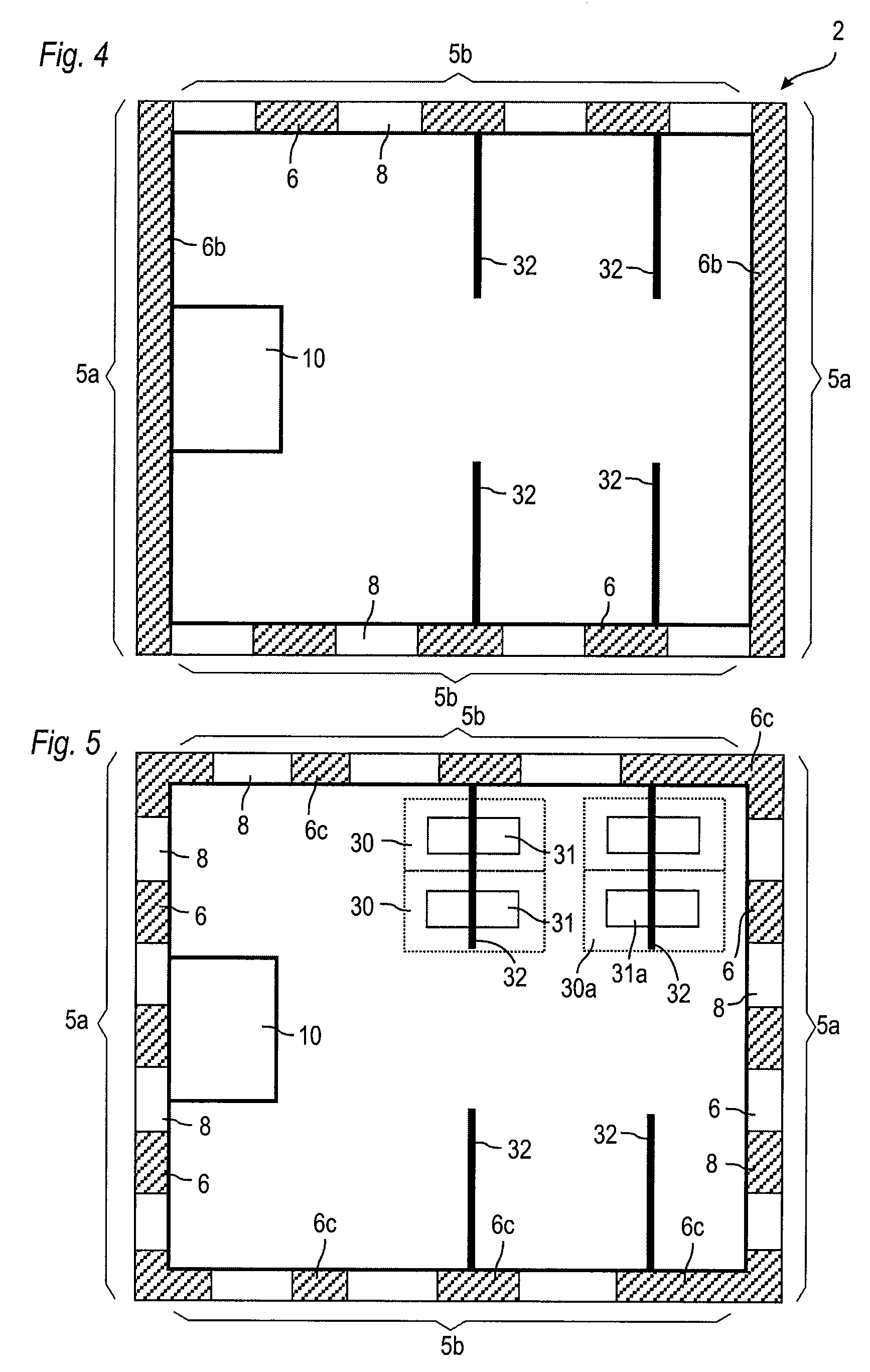
[0006]By providing high and low electrical resistance portions the resistance of the gate runner structure can be adjusted. This changes the effective gate resistance and, therefore, influences the switching behaviour of the semiconductor device. Steep oscillations can be avoided. Furthermore, the effective gate resistance can be varied according to specific needs so that tailored devices can be provided.

Problems solved by technology

For example, in non-optimised applications having relatively large parasitic inductances or capacitances a fast switching device can induce steep changes of the current and voltage which could result in high-frequent oscillations which may adversely affect the EMI-behaviour of the device or might bring the device outside of operational standards.
This, however, may cause significant changes to the layout of the device.

Method used


Image

  • Semiconductor device and method for manufacturing a semiconductor device
  • Semiconductor device and method for manufacturing a semiconductor device
  • Semiconductor device and method for manufacturing a semiconductor device

Examples


Embodiment Construction

[0019]Reference will now be made in detail to various embodiments, one or more examples of which are illustrated in the figures. Each example is provided by way of explanation, and is not meant as a limitation of the invention. For example, features illustrated or described as part of one embodiment can be used on or in conjunction with other embodiments to yield yet a further embodiment. It is intended that the present invention includes such modifications and variations. The examples are described using specific language which should not be construed as limiting the scope of the appending claims. The drawings are not scaled and are for illustrative purposes only.

[0020]The term “lateral” as used in this specification intends to describe an orientation parallel to the main surface of a semiconductor wafer or die.

[0021]The term “vertical” as used in this specification intends to describe an orientation which is arranged perpendicular to the main surface of the semiconductor wafer or ...


PUM


Abstract

A semiconductor device is provided which has a semiconductor substrate. An active cell area having at least one active cell is formed in the semiconductor substrate, wherein at least sections of the active cell area are surrounded by an edge termination region. An integrated gate runner structure is arranged at least partially in the edge termination region and has at least one low electrical resistance portion and at least one high electrical resistance portion which are electrically connected in series with each other.

Description

[0001]This description refers to embodiments of semiconductor devices and particularly to power semiconductor devices having an integrated gate runner structure with an adjusted gate resistance. Further embodiments refer to a method for manufacturing a semiconductor device.BACKGROUND OF THE INVENTION[0002]Power semiconductor devices such as compensation devices, also known as CoolMOS, exhibit a low specific on-state resistance (Ron*A) and can be formed at reduced size with respect to conventional MOSFETs while maintaining the low on-state resistance. The reduced size also results in smaller capacities which allow fast switching with steeper switching slopes.[0003]When using such high speed power semiconductor devices care must be taken to match the semiconductor device with parasitics in the application. For example, in non-optimised applications having relatively large parasitic inductances or capacitances a fast switching device can induce steep changes of the current and voltage ...

Claims


Application Information

Patent Timeline
IPC IPC(8): H01L29/00H01L21/3205
CPCH01L29/42372H01L29/42376H01L29/4238H01L29/7813H01L29/7803H01L29/7811H01L29/66712
Inventor KAINDL, WINFRIEDTREU, MICHAELKAPELS, HOLGERTOLKSDORF, CAROLINWILLMEROTH, ARMIN
Owner INFINEON TECH AUSTRIA AG
Learn More