Video surveillance system and method using ip-based networks

a video surveillance and network technology, applied in the field of video surveillance systems, can solve problems such as difficulty in processing large load by the camera, and achieve the effect of improving system scalability and preventing an increase in load of search systems

Active Publication Date: 2009-07-23
HITACHI LTD
View PDF33 Cites 58 Cited by
  • Summary
  • Abstract
  • Description
  • Claims
  • Application Information

AI Technical Summary

Benefits of technology

[0005]When the similarity search technique is implemented in the wide and large-scale monitoring system using the IP-based network, it is necessary to generate retrieval data (image feature) from the images captured by plural cameras and store the retrieval data in a database. As a result, the amount of computation required to extract the image feature and store the image feature in the database is increased. Therefore, it is necessary to reduce the amount of computation required for the search system to perform the extraction and the storage of the image feature.
[0009]According to the above-mentioned aspect of the invention, it is possible to prevent an increase in the load of a search system and improve the scalability of the system. In addition, it is possible to seamlessly search history information and real-time information.

Problems solved by technology

In addition, since an inexpensive camera sold on the market generally has a small amount of computation resource, it is difficult for the camera to process a large load.

Method used


Image

  • Video surveillance system and method using ip-based networks
  • Video surveillance system and method using ip-based networks
  • Video surveillance system and method using ip-based networks

Examples


first embodiment

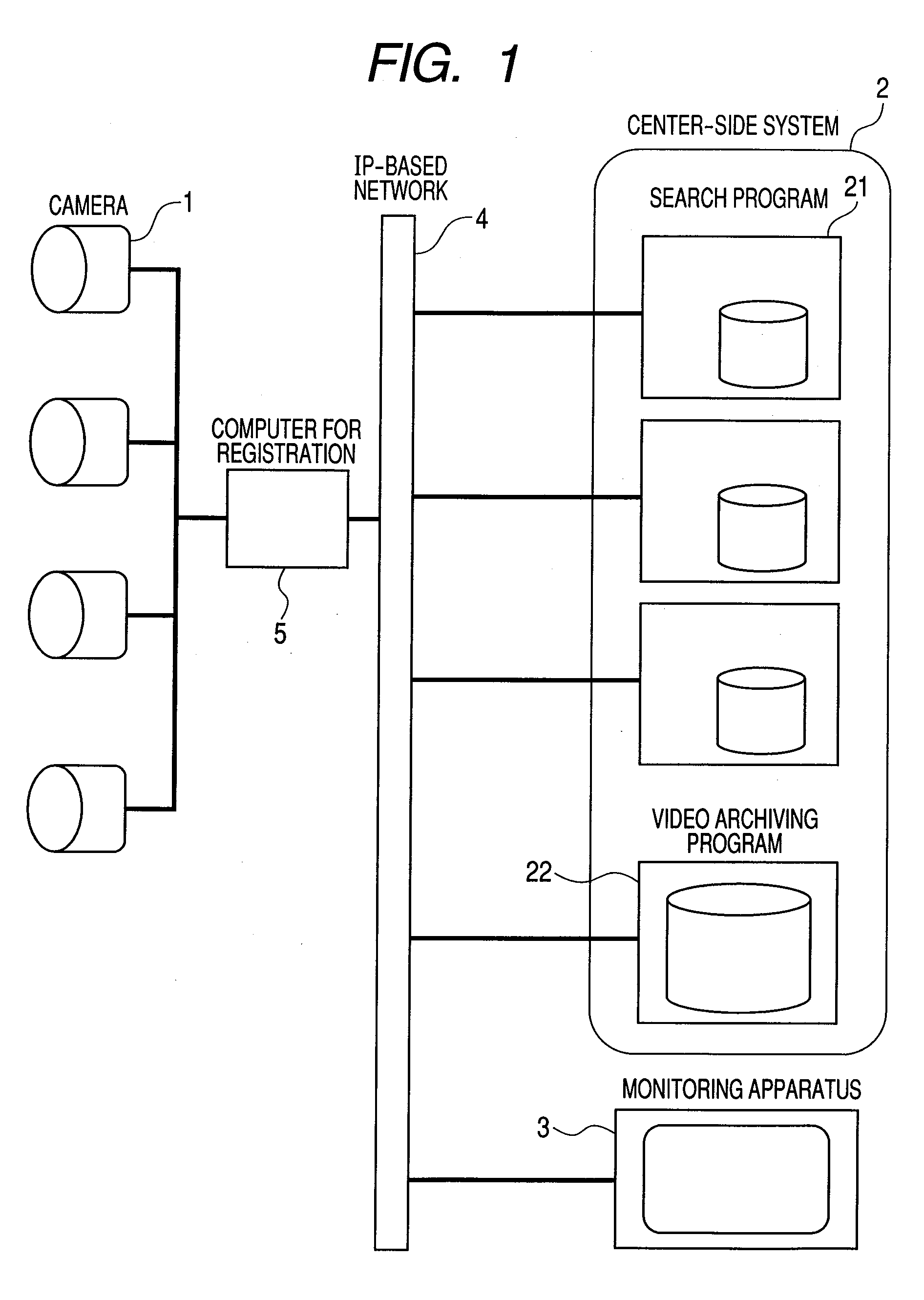
[0017]FIG. 1 is a block diagram illustrating the structure of a video surveillance system according to a first embodiment of the invention.

[0018]The video surveillance system according to the first embodiment includes plural cameras 1, a center-side system 2, a monitoring apparatus 3, an IP-based network 4, and a computer for registration 5.

[0019]The camera 1 includes an optical system including lenses, an imaging unit that converts an image into electric signals, and a network interface. For example, an IP camera that can be directly connected to an IP-based network may be used as the camera 1. The camera 1 is provided in an imaging target region, captures an image of the imaging target region, and transmits the captured image data to the computer for registration 5.

[0020]The computer for registration 5 is a computer including a processor, a memory, a storage device, and a network interface. The computer for registration 5 executes a program for image registration 100 (see FIG. 2) ...

second embodiment

[0072]FIG. 6 is a block diagram illustrating the structure of a video surveillance system according to a second embodiment of the invention.

[0073]The second embodiment differs from the first embodiment in that it does not include the computer for registration 5. In the second embodiment, an image processing unit provided in the camera 1 has the same function as the computer for registration 5 in the first embodiment.

[0074]Specifically, the video surveillance system according to the second embodiment includes plural cameras 1, a center-side system 2, a monitoring apparatus 3, and an IP-based network 4.

[0075]The camera 1 includes an optical system including lenses, an imaging unit that converts an image into electric signals, an image processing unit that processes captured image data, and a network interface. For example, an IP camera that can be directly connected to an IP-based network may be used as the camera 1. The camera 1 is provided in an imaging target region, captures an im...


PUM


Abstract

A technique capable of preventing an increase in the load of a system and a IP-based network that perform both a process of transmitting information in real time and a process of storing and searching history information and of improving the scalability of the system. A video surveillance system includes: plural cameras that capture images; a monitoring apparatus that displays the images captured by the cameras; an information generating apparatus that generates information for searching the images captured by the cameras; and a search apparatus that searches the images captured by the cameras. The information generating apparatus acquires the images captured by the cameras, generates retrieval data from the acquired images, and transmits the generated retrieval data to the search apparatus. The search apparatus stores the retrieval data received from the information generating apparatus in a storage device, and notifies the monitoring apparatus that the retrieval data has been stored.

Description

CLAIM OF PRIORITY[0001]The present application claims priority from Japanese patent application JP 2008-007934 filed on Jan. 17, 2008, the content of which is hereby incorporated by reference into this application.FIELD OF THE INVENTION[0002]The present invention relates to a video surveillance system including plural cameras.BACKGROUND OF THE INVENTION[0003]The development of an IP-enabled imaging apparatus, such as a Web camera, makes it possible to construct a wide and large-scale monitoring system using an IP-based network. In addition, a reduction in the cost of a hard disk device and an increase in the capacity of the hard disk device make it possible to store images captured by the monitoring system for a long time. In recent years, there is an increasing demand for a search technique capable of searching desired data from the stored image data.[0004]As a technique for searching images, there is a similarity search technique based on image features. In the search technique, a...

Claims


Application Information

Patent Timeline
Patent Type & Authority Applications(United States)
IPC IPC(8): H04N5/93G06T7/20G06F17/30H04N5/76H04N5/765H04N7/173H04N7/18H04N21/432H04N21/4545
CPCG06F17/30793G06F17/30811H04N5/91H04N5/765H04N5/772H04N5/76G06F16/784G06F16/786G08B13/19656G08B13/19608G08B13/19682G08B13/1968G08B13/19671G08B13/19663
Inventor HIROIKE, ATSUSHIKAGEHIRO, TATSUHIKOAKIRA, NAOTOTOUMURA, KUNIHIKOURANO, TAKEHIRO
Owner HITACHI LTD
Why Eureka
Try Eureka